

CNC Machined 6061 Aluminum Alloy Precision Heat Dissipation End Cover for Industrial Servo Motor
Description
Product Overview
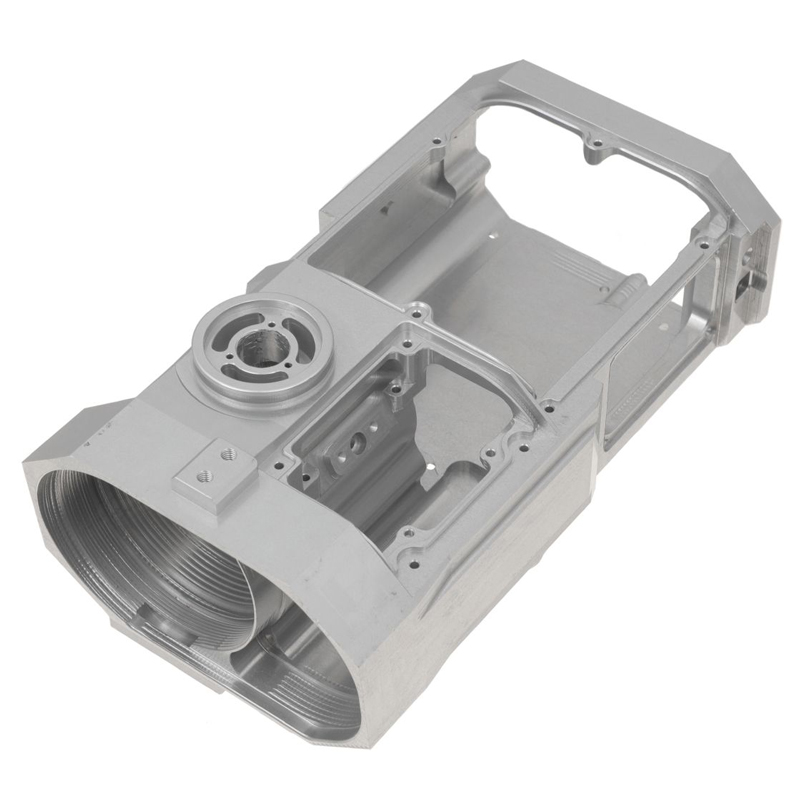
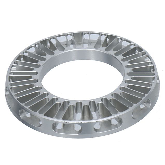
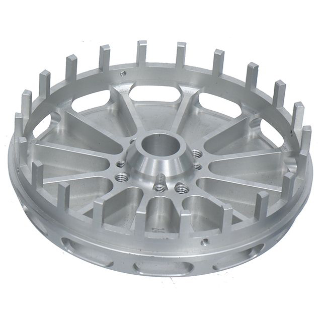
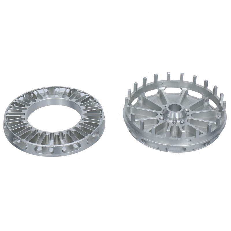
The CNC Machined 6061 Aluminum Alloy Precision Heat Dissipation End Cover is a critical component engineered for industrial servo motor systems. Installed at the front and rear of the servo motor housing, this end cover serves both as a protective enclosure and an active thermal management solution. Precision-machined from high-strength 6061 aluminum alloy using advanced 5-axis CNC technology, this component delivers exceptional dimensional accuracy, superior heat dissipation, and long-term reliability in demanding automation environments.
Leveraging the natural thermal conductivity of 6061-T6 aluminum—approximately 150–167 W/m·K, which is triple that of mild steel—this end cover efficiently draws heat away from internal stator windings and bearing assemblies, ensuring stable motor operation even under continuous high-load conditions. The lightweight yet robust construction reduces the system’s moment of inertia while maintaining structural integrity, making it ideal for compact motor assemblies in robotics, factory automation, and precision motion control applications.
CNC Machining Service Parameters
| Parameter | Standard Capability | High-Precision Capability | Notes |
|---|---|---|---|
| Material | Aluminum 6061-T6 | Aluminum 6061-T6 | Aerospace-grade, stress-relieved |
| Machining Process | 3-axis / 4-axis CNC | 5-axis CNC | Simultaneous multi-axis movement for complex geometries |
| Dimensional Tolerance | ±0.05 mm | ±0.01 mm to ±0.005 mm | Bearing chambers controlled within ±0.02 mm |
| Geometric Tolerance | ≤ 0.02 mm | ≤ 0.01 mm | Flatness, parallelism, perpendicularity |
| Surface Roughness (Ra) | 1.6 μm | 0.8 μm | Critical contact surfaces achieve Ra0.8 |
| Max Work Envelope | 1000 × 600 × 500 mm | 600 × 400 × 300 mm | Customizable based on motor frame size |
| Surface Treatment | Sandblasting | Anodizing (clear or color) | 10–15 μm anodizing thickness recommended |
| Prototype Lead Time | 3–5 working days | 5–7 working days | Depends on design complexity |
| Mass Production Lead Time | 10–15 days | 15–25 days | Subject to order quantity |
| Inspection | Standard CMM inspection | Full CMM + GD&T validation | 100% quality inspection before delivery |
| Typical Spindle Speed | 8,000 – 15,000 RPM | 10,000 – 20,000 RPM | Optimized for aluminum machining |
| Feed Rate | 800 – 2,000 mm/min | Optimized per geometry | Chip evacuation critical |
Application Scenarios
Industrial Automation & Robotics
Servo motors are the backbone of modern automation systems. This end cover is extensively used in robotic arms, pick-and-place systems, automated guided vehicles (AGVs), and assembly line equipment. The lightweight aluminum construction reduces the load on robotic joints, while the precision fit ensures smooth, vibration-free operation during continuous reversal movements.
CNC Machine Tools
In high-precision machining centers, servo motors drive spindle and axis movements. The end cover’s thermal management capabilities prevent heat accumulation that could compromise positioning accuracy, ensuring consistent machining quality over extended production runs.
Packaging & Material Handling Equipment
High-speed servo motors in packaging machinery generate significant heat. The optimized heat dissipation design of this end cover maintains motor temperatures within safe operating ranges, reducing downtime and extending service life.
Medical Device Manufacturing
Precision motion control in medical equipment demands both accuracy and reliability. The end cover’s tight tolerances and corrosion-resistant surface treatments make it suitable for cleanroom environments and critical medical applications.
Semiconductor & Electronics Manufacturing
Wafer handling, inspection equipment, and assembly systems rely on servo motors for precise positioning. The end cover’s thermal stability ensures consistent motor performance, directly impacting production yield and equipment uptime.
Material Analysis: 6061-T6 Aluminum Alloy
Chemical Composition (Nominal)
| Element | Percentage |
|---|---|
| Aluminum (Al) | 95.8 – 98.6% |
| Magnesium (Mg) | 0.8 – 1.2% |
| Silicon (Si) | 0.4 – 0.8% |
| Iron (Fe) | ≤ 0.7% |
| Copper (Cu) | 0.15 – 0.4% |
| Chromium (Cr) | 0.04 – 0.35% |
| Zinc (Zn) | ≤ 0.25% |
| Titanium (Ti) | ≤ 0.15% |
| Manganese (Mn) | ≤ 0.15% |
Physical & Mechanical Properties
| Property | Value | Significance for End Cover |
|---|---|---|
| Density | 2.70 g/cm³ | 1/3 the weight of steel, reduces motor inertia |
| Thermal Conductivity | 150 – 167 W/m·K | Triple that of mild steel; superior heat dissipation |
| Thermal Expansion Coefficient | 23.6 μm/m·°C | Requires thermal management during machining |
| Yield Strength | 241 – 276 MPa | Adequate structural strength for motor enclosures |
| Tensile Strength | 290 – 310 MPa | Robust enough for industrial environments |
| Hardness (Brinell) | 95 HB | Good wear resistance for bearing interfaces |
| Elastic Modulus | 68.9 GPa | Lower than steel, requires careful fixturing |
| Corrosion Rate (ASTM B117) | 0.10 mm/year | Excellent corrosion resistance; natural oxide layer |
Why 6061-T6?
6061-T6 is the most widely used aluminum alloy in CNC machining due to its exceptional balance of strength, machinability, and cost-effectiveness. For servo motor end covers specifically:
-
Superior Thermal Conductivity: Rapid heat dissipation prevents thermal damage to motor windings and bearings.
-
Excellent Machinability: Achieves the highest material removal rate (7.5 mm³/min) among common engineering materials with surface roughness as low as Ra0.58 μm.
-
Dimensional Stability: Low thermal expansion coefficient minimizes warping during precision machining.
-
Natural Corrosion Resistance: The self-healing aluminum oxide layer provides protection in humid industrial environments.
-
Anodizing Compatibility: Accepts clear or colored anodizing for enhanced surface hardness and aesthetics.
Tolerance Capability
Dimensional Tolerances
| Feature Type | Standard Tolerance | High-Precision Tolerance | Criticality |
|---|---|---|---|
| Bearing Chamber Diameter | ±0.02 mm | ±0.005 mm | Critical for bearing fit and motor concentricity |
| Mounting Hole Positions | ±0.05 mm | ±0.01 mm | Ensures proper motor assembly alignment |
| Overall Dimensions | ±0.05 mm | ±0.01 mm | Housing integration |
| Fin Thickness | ±0.02 mm | ±0.01 mm | Heat dissipation consistency |
| Threaded Features | Class 6H | Class 4H | Secure fastening |
Geometric Tolerances (GD&T)
| Feature | Standard | High-Precision | Standard Reference |
|---|---|---|---|
| Flatness (Mounting Face) | ≤ 0.02 mm | ≤ 0.01 mm | ISO 1101 |
| Parallelism | ≤ 0.02 mm | ≤ 0.01 mm | Critical for bearing alignment |
| Perpendicularity | ≤ 0.02 mm | ≤ 0.01 mm | Mounting hole orientation |
| Concentricity | ≤ 0.02 mm | ≤ 0.01 mm | Rotor/stator alignment |
| Cylindricity (Bearing Bore) | ≤ 0.015 mm | ≤ 0.008 mm | Bearing fit and rotation smoothness |
Quality Assurance
All critical dimensions are verified using coordinate measuring machines (CMM) with in-process inspections throughout the machining cycle. Statistical process control (SPC) ensures batch-to-batch consistency with CpK ≥ 1.33 for production runs.
Manufacturing Challenges & Solutions
Challenge 1: Thermal Deformation During Machining
The Problem: Aluminum 6061 has a thermal expansion coefficient of 23.6 μm/m·°C. A 300 mm component experiencing a 10°C temperature change can expand approximately 0.069 mm, which is enough to violate tight flatness and dimensional tolerances. The primary challenge in machining 6061 aluminum is controlling temperature influence throughout the process.
Our Solutions:
-
Climate-controlled machining facilities (±1°C stability) eliminate thermal drift.
-
“Rough-Rest-Finish” strategy: Rough machining removes bulk material, the part is allowed to rest and release internal stresses, followed by finishing passes.
-
High-pressure through-spindle coolant systems manage cutting zone temperatures.
-
Symmetrical material removal balances stress distribution and prevents warping.
Challenge 2: Thin-Wall & Fin Deformation
The Problem: Heat dissipation end covers typically feature thin fins and walls (often 0.5 mm or less). Material deflects under cutting forces and recovers after the tool passes, leading to dimensional inaccuracies. Long, thin fins are also prone to vibration during machining, causing surface defects and dimensional inconsistency.
Our Solutions:
-
Separating roughing and finishing operations with controlled machining allowance.
-
Applying stress relief (natural or artificial aging) between operations.
-
Custom fixture solutions with temporary support structures that stabilize fins during machining.
-
Optimized toolpaths with smooth spiral entry and evenly distributed cutting forces.
-
5-axis machining ensures optimal tool angles, minimizing deflection while maintaining surface roughness at Ra0.8 or better.
Challenge 3: “Gummy” Behavior & Built-Up Edge
The Problem: 6061 aluminum has a tendency to stick to cutting tools, leading to built-up edge (BUE) that compromises surface finish and dimensional accuracy.
Our Solutions:
-
Sharp, polished carbide cutters with high helix angles minimize material adhesion.
-
Optimized cutting parameters (high spindle speed, appropriate feed rates) reduce friction and heat.
-
Proper coolant concentration (optimal at 11%) enhances chip evacuation and surface quality.
Challenge 4: Residual Stress & Warping
The Problem: Standard extruded or rolled 6061-T6 bar stock contains internal stresses from the mill’s manufacturing process. When material is removed, these stresses are released, causing the part to warp—the infamous “potato chip” effect.
Our Solutions:
-
Roughing pass leaving 0.5–1.0 mm of extra material, followed by stress relaxation period.
-
Light reclamping and finishing pass to achieve final tolerances.
-
Pre-machining stress relief through controlled thermal treatment when required.
Challenge 5: Maintaining Bearing Chamber Precision
The Problem: The bearing chamber is the most critical feature of the end cover. Requirements for dimensional accuracy and geometric tolerances are extremely stringent, with parallelism and flatness of related planes strictly controlled.
Our Solutions:
-
Single-setup 5-axis machining minimizes cumulative errors from repositioning.
-
Dedicated precision boring operations for bearing chambers.
-
100% CMM inspection of critical bearing interfaces.
Frequently Asked Questions
Q1: What is the standard material for this end cover?
The standard material is Aluminum 6061-T6, which offers an optimal balance of thermal conductivity, machinability, strength, and corrosion resistance. 7075 aluminum is available upon request for applications requiring higher strength.
Q2: What tolerances can you achieve on the bearing chamber?
Bearing chambers are typically controlled within ±0.02 mm standard, with high-precision capability down to ±0.005 mm on critical dimensions. Geometric tolerances such as cylindricity and concentricity are maintained at ≤ 0.01 mm.
Q3: What surface treatments are available?
Options include natural anodizing, colored anodizing (various colors), sandblasting, and electrophoresis. Recommended anodizing thickness is 10–15 μm to balance wear resistance and thermal performance.
Q4: How does the end cover manage heat dissipation?
6061-T6 aluminum conducts heat at 150–167 W/m·K, which is triple the thermal conductivity of mild steel. The end cover’s design incorporates optimized fin geometries and surface area to maximize heat transfer from the motor to the surrounding environment.
Q5: What is the typical lead time for prototypes?
Prototype lead time ranges from 3–7 working days depending on design complexity. Mass production lead time is typically 10–25 days subject to order quantity.
Q6: Can you customize the end cover design?
Yes, we accept custom designs based on 2D drawings (PDF, JPG, DWG) or 3D models (STP, IGS). Our engineering team provides Design for Manufacturability (DFM) analysis to optimize part geometry for machinability and cost-effectiveness.
Q7: How do you ensure quality and consistency?
We utilize over 30 high-precision 3D/2D inspection instruments and coordinate measuring machines (CMM) for in-process and final verification. All parts undergo 100% quality inspection before delivery, with full inspection reports provided.
Q8: What file formats do you accept for quotations?
We accept 2D drawings in PDF, JPG, and DWG formats, as well as 3D models in STP and IGS formats.
Q9: What industries use this end cover?
Applications span industrial automation, robotics, CNC machine tools, packaging equipment, medical device manufacturing, semiconductor equipment, and automotive production systems.
Q10: Why choose CNC machining over die casting for this component?
CNC machining offers superior dimensional accuracy, tighter tolerances, better surface finish, and greater design flexibility compared to die casting. While die casting is economical for high volumes, CNC machining is preferred for precision-critical applications where tolerance, concentricity, and thermal performance are paramount.
Additional information
| material |
|---|
soips_cker –
Very professional