
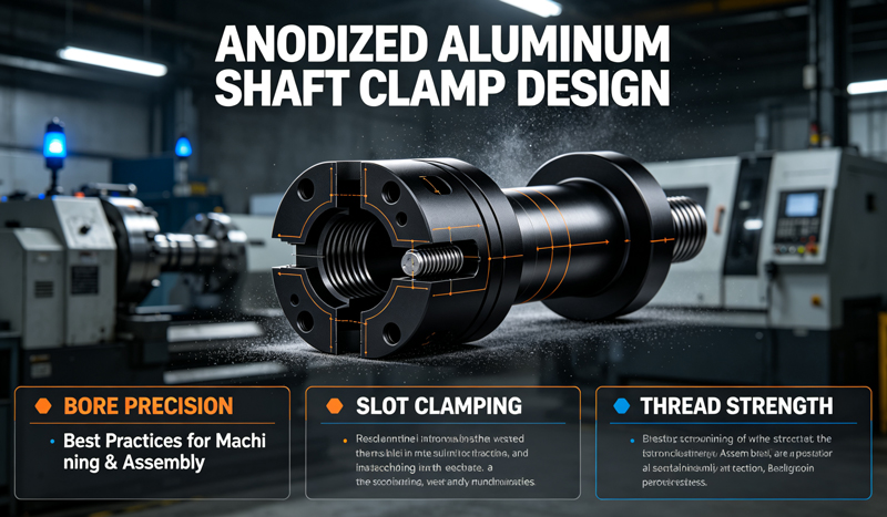
Anodized aluminum shaft clamps are essential components in industrial automation, robotics, and precision motion-control systems. These split-clamp blocks secure round shafts, guide rods, and sensor assemblies through mechanical compression.
When properly designed, they provide uniform clamping force without damaging the shaft surface. However, poor design choices in bore tolerance, split slot geometry, and threaded holes can lead to slipping shafts, thread stripping, uneven clamping, and premature part failure.
This guide outlines proven best practices for designing anodized aluminum shaft clamps, with a focus on the three critical features: bore, slot, and threads.
Table of Contents
ToggleThe Critical Factor: Anodizing Changes Dimensions
Understanding how anodizing affects aluminum dimensions is the foundation of good shaft clamp design. The anodizing process builds an oxide layer on the aluminum surface, with part of the coating growing inward and part growing outward.
Type II Anodizing
For Type II decorative anodizing, coating thickness is typically around 5–25 μm. Dimensional change is relatively small but can still affect precision features such as bores and threads.
Type III Hardcoat Anodizing
For Type III hardcoat anodizing, coating thickness is typically around 25–100 μm. The dimensional effect can be significant for bores, threads, and sliding clearances.
For shaft clamps, where bores must fit tightly on shafts and threads must accept screws, even a few microns of dimensional change can mean the difference between a proper fit and a failed assembly.
1. Bore Design: Getting the Fit Right
The central bore is the core functional feature of an aluminum shaft clamp. Its tolerance, surface finish, and edge treatment directly determine holding performance.
Bore Tolerance Recommendations
For standard smooth solid shafts with h7/h8 shaft tolerance, the bore can be designed around H7 or H8 tolerance, depending on the required fit and clamping mechanism.
A bore that is too loose can allow shaft movement under vibration, while an excessively tight bore can make shaft insertion difficult before the clamp is tightened.
For high-precision positioning applications, an H7 bore with an h6 shaft may be considered to minimize radial clearance and improve positioning accuracy.
Critical rule: Avoid designing an interference fit without considering the split slot’s compression. A shaft clamp relies on controlled clearance before the clamping screw is tightened.
Accounting for Anodizing
Anodizing adds an aluminum oxide layer to the surface. Typical coating thicknesses are approximately 5–25 μm for Type II and 25–100 μm for Type III, depending on the specified process.
Always account for anodizing when designing the final bore diameter.
There are three common strategies:
Pre-anodizing compensation — Machine the bore with an appropriate dimensional allowance so the final dimension falls within specification after anodizing.
Post-anodizing reaming or finishing — For certain precision applications, leave a controlled amount of stock and finish the bore after anodizing.
Masking — Mask the bore during anodizing to prevent coating buildup on critical mating surfaces. This provides reliable dimensional control but can increase finishing costs.
Drawing requirement: Always specify whether the critical bore dimension applies before anodizing or after anodizing. This simple note can prevent many assembly problems.
Bore Edge Treatment
Add a small chamfer, such as 0.5 × 45°, to the bore entry.
A bore chamfer helps:
Prevent sharp edges from scratching the mating shaft
Remove machining burrs
Improve shaft insertion
Reduce the risk of uneven coating accumulation at sharp edges
Common mistake: Using a sharp, zero-chamfer bore. Burrs can damage the shaft surface, while sharp edges can also produce less uniform anodizing.
Bore Roundness and Surface Finish
For precision motion systems, bore quality is as important as bore diameter.
A poorly machined bore can cause:
Uneven shaft contact
Shaft misalignment
Reduced clamping efficiency
Increased runout
Localized contact stress
For precision assemblies, specify appropriate roundness, cylindricity, and surface finish requirements on the engineering drawing. A surface finish such as Ra 1.6 μm may be suitable for many machined aluminum clamp applications, although the actual requirement should be determined by the shaft and application.
2. Split Slot Design: Controlling Clamping Force
The split slot enables controlled elastic deformation of the clamp body. Slot width, depth, and termination geometry directly affect clamping force distribution and service life.
Slot Width
For small-to-medium aluminum shaft clamp blocks, a starting design range of approximately 0.8–1.5 mm may be considered.
The actual slot width should be validated according to the clamp’s diameter, wall thickness, screw size, material, and required clamping force.
A slot that is too narrow may provide insufficient elastic travel, making it difficult for the screw to generate adequate compression.
A slot that is too wide can reduce structural rigidity and may cause excessive deformation or permanent yielding after repeated tightening.
Slot Termination Relief Hole
A round relief hole at the end of the slot is recommended for many split-clamp designs.
The relief hole helps reduce stress concentration at the slot termination and can improve fatigue resistance during repeated tightening cycles.
A practical starting point is:
Relief hole diameter ≥ 2 × slot width
The exact geometry should be validated based on the clamp’s size and loading conditions.
Design check: After the screw reaches the specified tightening torque, the slot should not necessarily close completely. A controlled residual gap can indicate that the clamp is relying on elastic deformation rather than excessive crushing of the aluminum.
If the slot closes completely before the required clamping force is achieved, review the slot width, wall thickness, bore clearance, and screw configuration.
Slot Position Relative to the Bore
The split slot should intersect the central bore while maintaining sufficient material around the remaining body of the clamp.
Avoid cutting the slot so deeply that the remaining wall becomes excessively thin.
Insufficient wall thickness can result in:
Permanent deformation
Reduced clamping force
Cracking
Thread distortion
Reduced fatigue life
The final wall thickness should be determined according to the material, shaft diameter, clamp dimensions, screw preload, and operating loads.
3. Thread Design: Avoiding Stripping and Jamming
Two types of threads are commonly found on shaft clamps:
Clamping screw threads — Used to close the split slot and generate radial clamping force.
Mounting threads — Used to secure the clamp to a base plate, bracket, fixture, or machine structure.
These threads may have different loading requirements and should be evaluated separately.
Thread Engagement Depth
For 6061-T6 aluminum, a useful preliminary design guideline is approximately 1.5 × the screw nominal diameter for effective thread engagement when relatively high tightening loads are expected.
For example:
| Screw Size | Approximate Minimum Engagement |
|---|---|
| M3 | 4.5 mm |
| M4 | 6.0 mm |
| M5 | 7.5 mm |
| M6 | 9.0 mm |
| M8 | 12.0 mm |
These are design guidelines rather than universal requirements. Actual thread engagement should be verified against screw preload, aluminum strength, thread class, joint design, and tightening torque.
Because aluminum has lower thread shear strength than steel, insufficient engagement can increase the risk of thread stripping.
For high-cycle applications, consider using a threaded insert when the available wall thickness or engagement length is limited.
Thread Placement
Thread location is important because the clamp body deforms during tightening.
When positioning threads:
Keep critical threads away from the highest-deformation region around the split slot.
Maintain sufficient material around threaded holes.
Avoid placing threads too close to the bore.
Keep mounting holes away from major stress concentrations where possible.
Verify that tightening the screw will not distort the threaded hole.
Managing Anodizing on Threads
Anodizing can build a coating inside threaded holes and reduce available thread clearance.
Two common approaches are available.
Option 1: Mask the Threads Before Anodizing
Threads can be protected using suitable masking plugs or other production masking methods.
Advantages include:
No anodizing buildup inside the thread
More predictable screw fit
Better dimensional control
No need to remove the coating after anodizing
This approach is particularly useful for production parts where consistent assembly is important.
Option 2: Tap or Chase the Thread After Anodizing
For prototypes or low-volume parts, the thread can be cleaned or chased after anodizing to restore the required fit.
However, this removes the anodized layer from the thread surface and therefore changes the local surface-treatment condition.
The preferred method should depend on the required corrosion resistance, production volume, dimensional requirements, and assembly process.
Common mistake: Tapping the thread before anodizing without specifying masking or post-treatment thread control. Coating buildup can reduce thread clearance and cause screws to jam or cross-thread during assembly.
Countersinks and Counterbores
Socket-head cap screws with counterbores are common in industrial CNC shaft clamps because they provide high clamping force while keeping the assembly compact.
The counterbore should provide adequate clearance for:
Screw head diameter
Screw head height
Hex-key or tool access
Assembly clearance
Washer clearance, if required
A properly designed counterbore also helps keep the screw head below or flush with the surrounding surface when required by the application.
Material Selection
6061-T6 Aluminum
6061-T6 aluminum is one of the most commonly selected materials for CNC machined shaft clamps.
It provides a good balance of:
CNC machinability
Mechanical strength
Elastic deformation performance
Corrosion resistance
Anodizing compatibility
Material availability
Cost efficiency
For general industrial automation, robotics, fixtures, and motion-control applications, 6061-T6 is often an excellent starting point.
7075-T6 Aluminum
7075-T6 aluminum can be considered when higher mechanical strength and weight reduction are important.
Compared with 6061-T6, 7075-T6 generally offers higher strength but can have higher material cost and different corrosion/anodizing considerations.
It is more appropriate for demanding applications where the additional mechanical performance justifies the material premium.
Anodizing Selection for Shaft Clamps
The anodizing specification should be selected according to the actual operating environment.
| Anodizing Type | Typical Thickness | Typical Application |
|---|---|---|
| Type II | Approximately 5–25 μm | General industrial and decorative applications |
| Type III | Approximately 25–100 μm | Wear-resistant and demanding industrial applications |
When specifying anodizing, the engineering drawing should identify:
Anodizing type
Coating thickness
Color
Surface preparation
Masking requirements
Critical dimensions after coating
For precision shaft clamps, masking the bore or threads may be appropriate when coating buildup would interfere with assembly.
CNC Machining Considerations
Anodized aluminum shaft clamps are well suited to CNC milling, but certain design features can increase machining difficulty and cost.
Deep Bores and Pockets
Deep internal features may require long-reach tools. Tool deflection and vibration can reduce dimensional accuracy and surface finish.
Thin Clamp Walls
Thin walls can deform or vibrate during CNC machining. Maintaining adequate wall thickness improves machining stability and final dimensional accuracy.
Tight Bore Tolerances
Precision bores may require separate roughing and finishing operations to achieve the required dimensional and geometric tolerances.
Multiple Machining Setups
If a shaft clamp contains features on multiple faces, additional setups may be necessary.
Whenever possible, design the component so that critical features can be machined in fewer setups. This can reduce:
Setup time
Machining cost
Positioning errors
Production variability
Design for Manufacturability (DFM)
When designing an anodized aluminum shaft clamp for CNC machining, consider the following DFM principles:
Keep the bore accessible to standard cutting tools.
Avoid unnecessarily deep pockets.
Use standard drill and thread sizes where possible.
Add appropriate internal corner radii.
Maintain sufficient material around threaded holes.
Avoid extremely thin walls.
Keep critical features accessible in the same machining setup when possible.
Clearly specify post-anodizing dimensions.
Identify surfaces that require masking.
Use realistic tolerances.
Avoid unnecessary cosmetic requirements on non-functional surfaces.
A DFM review before production can identify potential machining and finishing problems before they become costly production issues.
Design Checklist for Production
Before releasing an anodized aluminum shaft clamp for CNC production, verify the following:
Bore tolerance is clearly specified.
Bore dimensions account for anodizing.
Drawing specifies whether critical dimensions are before or after anodizing.
Bore chamfer is included where appropriate.
Bore roundness and surface finish requirements are specified for precision applications.
Split slot width has been evaluated according to the clamp geometry.
Slot termination includes an appropriate stress-relief feature where required.
Remaining wall thickness is sufficient for the expected clamping load.
Thread engagement is sufficient for the selected aluminum alloy and screw.
Thread locations do not interfere with high-deformation areas.
Thread masking or post-anodizing thread treatment is specified.
Counterbore or countersink provides sufficient screw-head and tool clearance.
Anodizing type and coating thickness are clearly specified.
Critical machining tolerances are identified.
CNC tool access and machining setups have been considered.
Conclusion
Designing reliable anodized aluminum shaft clamps requires a systematic approach to managing the dimensional effects of anodizing while maintaining sufficient mechanical strength and manufacturability.
The three most important design areas are the bore, split slot, and threads. The bore must provide the correct shaft fit and account for coating thickness. The split slot must provide controlled elastic deformation without weakening the clamp body. Threads must provide sufficient engagement and maintain reliable screw fit after anodizing.
For custom CNC machining production, the best results come from balancing functional tolerances, structural integrity, anodizing requirements, and manufacturability.
Providing your CNC machining partner with clear dimensional requirements—including whether critical dimensions apply before or after anodizing—can significantly reduce assembly problems and unnecessary production costs.
For more technical articles on machining processes, tolerances, and surface finishing, explore our CNC Machining Guide.
Looking for CNC Machining Support for Custom Shaft Clamps?
XINQIDA provides precision CNC milling and CNC machining services for custom aluminum shaft clamps, split-clamp blocks, mounting components, and other non-standard mechanical parts.
Our engineering team can review your 2D drawings, 3D CAD files, bore tolerances, slot geometry, thread requirements, anodizing specifications, and DFM considerations before production.
Contact our engineering team for a CNC machining and manufacturability review of your custom shaft clamp design.


Really helpful post. If you need text-to-video at 480P/768P, check out H3MaxAI at . H3MaxAI