
CNC Machined Split Clamp Block – Aluminum Shaft Clamp with Anodized Finish for Industrial Automation
Description
Product Overview
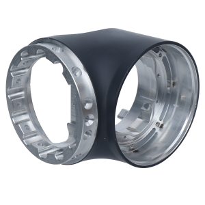
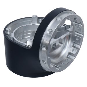
This custom CNC machined split clamp block is designed to securely hold and position cylindrical shafts, rods, guide posts, and other round mechanical components used in industrial automation and motion control equipment.
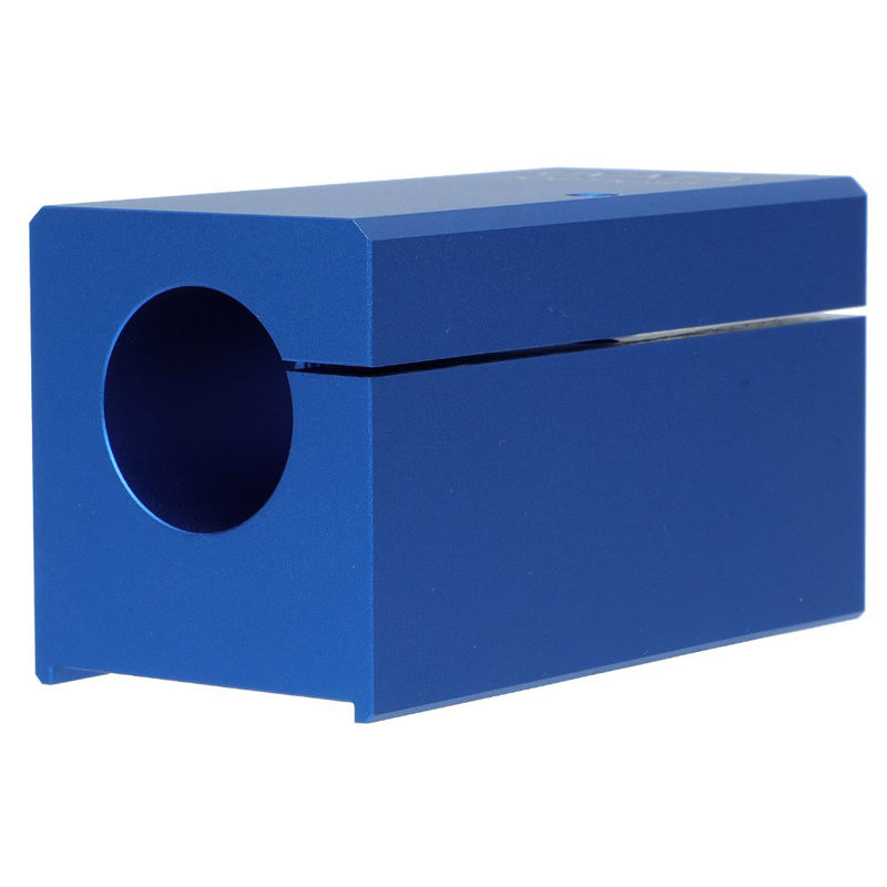
The split clamp block features a precision-machined bore with an open split section that allows the bore to close slightly when the clamping fastener is tightened. This generates controlled radial clamping force around the shaft, providing secure and repeatable positioning without the need for additional external clamping hardware.
Manufactured from CNC-machined aluminum, the split clamp block offers a lightweight yet rigid construction suitable for automation equipment, machine frames, fixtures, linear motion systems, and custom mechanical assemblies. An anodized finish improves surface durability and corrosion resistance while providing a clean, consistent appearance.
The component can be customized with different bore diameters, mounting-hole patterns, threaded holes, split configurations, and overall dimensions to match the customer’s engineering drawing. Critical features such as the clamping bore diameter, split geometry, mounting-hole position, bore-to-mounting-face relationship, and perpendicularity can be controlled to support accurate assembly and reliable shaft alignment.
Whether used for shaft positioning, guide-rod fixation, fixture mounting, or mechanical adjustment, this custom split clamp block can be manufactured in prototype and small-batch quantities according to application requirements and technical drawings.
This split shaft clamp block is part of our CNC Block product line, which covers custom machined blocks, fixture blocks, and mounting blocks for industrial automation and machinery applications.
CNC Machining Services & Technical Specifications
| Parameter | Typical Specification |
|---|---|
| Part Name | Split Shaft Clamp Block |
| Manufacturing Process | CNC Milling |
| Secondary Processes | CNC Drilling, Threading, Boring / Reaming as Required |
| Recommended Material | Aluminum 6061-T6 |
| Other Aluminum Options | 6063, 6082, 7075 and other grades available |
| Surface Finish | Anodizing |
| Anodizing Options | Type II or Type III depending on application |
| Typical Color | Blue, Black, Natural, Red or Custom |
| General Machining Tolerance | ±0.05 mm typical |
| Precision / Critical Features | Up to ±0.01 mm or tighter when specified and technically suitable |
| Critical Bore | Controlled according to shaft fit requirement |
| Threaded Features | Metric or Imperial threads |
| Surface Roughness | Typically Ra 1.6–3.2 μm on machined surfaces |
| Flatness | Controlled according to drawing and functional requirements |
| Perpendicularity | Controlled on mounting and locating surfaces as required |
| Edge Treatment | Deburring and edge breaking |
| Inspection | Dimensional inspection, thread inspection and visual inspection |
| Inspection Equipment | CMM, height gauge, micrometer, caliper, bore gauge and thread gauges as required |
| Production Volume | Prototype, Low Volume, Small Batch and Production Runs |
| Drawing Formats | STEP, STP, IGES, X_T, DWG, DXF and PDF |
| Customization | Fully customized to customer drawings or 3D CAD files |
Actual tolerances depend on part geometry, material, feature size, machining process, quantity, and drawing requirements. Critical dimensions should be identified on the engineering drawing rather than applying a tight tolerance to every feature.
Material Analysis: Why Aluminum Is Suitable for This Clamp Block
Aluminum is a practical material choice for shaft clamp blocks used in automation equipment because it provides a useful combination of strength, low weight, machinability, and corrosion resistance.
Aluminum 6061-T6
6061-T6 is a common choice for this type of CNC machined component.
Its advantages include:
- Good machinability for CNC milling and drilling
- Good strength-to-weight ratio
- Relatively low density
- Good dimensional stability for typical automation components
- Good corrosion resistance
- Excellent compatibility with anodizing
- Wide availability and cost-effective production
For general industrial automation equipment, 6061-T6 offers a good balance between mechanical performance and manufacturing cost.
Aluminum 7075
When higher strength is required, 7075 aluminum can be considered.
7075 is particularly useful when the clamp must withstand higher mechanical loads while maintaining a relatively low component weight. However, it is generally more expensive than 6061-T6, so it should be selected based on actual load requirements rather than simply choosing the highest-strength alloy.
Aluminum 6082
For some European industrial applications, 6082 aluminum can also be considered where availability, strength, and machinability make it appropriate for the application.
The final material should always be selected according to the shaft load, clamping force, operating environment, corrosion requirements, and applicable engineering specifications.
Why Anodizing Is Used
The anodized finish provides more than a cosmetic appearance.
For an aluminum shaft clamp block, anodizing can improve:
- Surface hardness
- Wear resistance
- Corrosion resistance
- Surface durability
- Appearance and color consistency
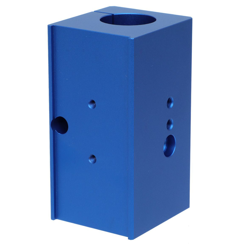
Blue anodizing, as shown on this component, is commonly used when visual identification or a specific equipment appearance is required.
For components subjected to higher wear or more demanding environments, the appropriate anodizing specification should be selected according to the required coating thickness, hardness, dimensional impact, and operating conditions.
Anodizing vs. Alternative Surface Finishes
While anodizing is the preferred finish for this split shaft clamp block, it is not the only surface treatment available for CNC machined aluminum components. Depending on your application’s wear profile, corrosion environment, electrical conductivity requirements, cosmetic goals, and budget, powder coating, e-coating, or passivation may also be viable options.
For example, if the clamp block requires strict dimensional control on the clamping bore after coating, passivation may preserve tolerances better than a thicker anodized layer. Conversely, if the part will be exposed to outdoor or corrosive environments, a Type III hard anodize or powder coating may offer superior protection.
To help you select the right finish for your aluminum CNC parts, we have prepared a detailed engineering comparison covering coating thickness, surface hardness, wear resistance, corrosion performance, dimensional impact, electrical conductivity, and relative cost. Read our guide on anodizing vs. powder coating, e-coating, and passivation for CNC aluminum parts to make an informed surface finish decision.
Key Machining Features
This part contains several features that require controlled CNC machining operations. For engineering guidance on bore sizing, split-slot geometry, and thread placement, see our article on anodized aluminum shaft clamp design best practices.
Precision Central Bore
The central bore is one of the most important functional features because it interfaces directly with the shaft or cylindrical component.
The required bore tolerance should be determined from the shaft diameter and desired fit. Depending on the application, the bore may require CNC boring, reaming, or a controlled finishing operation after rough milling.
Split Clamping Slot
The narrow split slot allows the clamp body to deform slightly when the clamping fastener is tightened.
The slot width, depth, position, and relationship to the central bore must be controlled carefully. Excessive material removal can reduce clamping stiffness, while insufficient clearance may prevent the clamp from generating the required holding force.
Threaded Mounting Holes
The multiple threaded holes allow the component to be attached to surrounding machine structures.
Thread size, depth, hole location, and perpendicularity are important because an error in the mounting pattern can create assembly problems even when the external dimensions of the component are correct.
Cross-Drilled Features
The side holes require accurate positioning relative to the central bore and other mounting features. Depending on the design, these holes may be used for clamping screws, mounting hardware, alignment components, or other mechanical connections.
Manufacturing Challenges
1. Maintaining Bore Accuracy
The central bore is a functional feature, so its diameter cannot be treated as an ordinary cosmetic dimension.
Tool deflection, thermal expansion, workholding deformation, and finishing operations can all influence bore accuracy. For tighter requirements, the machining sequence should be designed around the final bore specification rather than simply milling the feature in one operation.
2. Controlling the Split Slot
The split slot creates a relatively thin section in the clamp body.
If the workpiece is not adequately supported during machining, cutting forces can cause vibration or slight deformation. Tool selection, machining parameters, workholding, and machining sequence therefore need to be considered together.
3. Thread-to-Bore Alignment
The relationship between the clamping threads and central bore directly affects how the clamp applies force to the shaft.
Incorrect positioning can result in uneven clamping or poor assembly performance. The thread locations should therefore be inspected relative to the functional bore rather than inspected only as independent dimensions.
4. Multiple-Surface Machining
The component contains features on several sides. Maintaining the positional relationship between the central bore, side holes, threaded holes, and mounting surfaces requires a controlled machining sequence.
For higher-precision requirements, multi-axis CNC machining or carefully planned multiple setups can reduce setup-related positional errors.
5. Anodizing Dimensional Considerations
Anodizing adds a controlled surface layer to aluminum.
For general external surfaces this is usually straightforward, but functional bores, threaded holes, and close-fitting surfaces may require special consideration. Masking, post-processing, or dimensional compensation may be necessary when coating thickness could affect the required fit.
Recommended CNC Machining Process
A typical manufacturing sequence for this type of component may include:
- Aluminum material preparation
- CNC face milling and squaring
- Rough milling of the external profile
- CNC drilling of mounting and cross holes
- CNC tapping of threaded holes
- Machining of the central bore
- Machining of the split clamping slot
- Precision finishing of critical surfaces
- Deburring and edge breaking
- Dimensional inspection
- Anodizing
- Final inspection and visual inspection
- Packaging for shipment
The exact sequence is adjusted according to the drawing, tolerance requirements, quantity, and surface-treatment specification. For a broader overview of CNC machining processes, material selection, tolerance standards, and design best practices, refer to our CNC Machining Guide.
Applications
Custom CNC machined split shaft clamp blocks can be used in a variety of mechanical and automation systems, including:
Industrial Automation Equipment
Used to secure shafts, guide rods, support components, and mechanical positioning elements inside automated machinery.
Linear Motion Systems
Suitable for applications involving guide shafts, linear mechanisms, positioning systems, and machine slides where accurate shaft support and positioning are required.
Robotic Equipment
Can be used as a mechanical mounting or shaft-support component in robotic peripheral equipment, end-of-arm tooling, and automated positioning mechanisms.
Assembly Machines
Useful for securing shafts and cylindrical components within automated assembly stations and production equipment.
Inspection and Test Equipment
The rigid machined body and multiple mounting interfaces make this type of component suitable for custom inspection fixtures, test equipment, and positioning assemblies.
Custom Machinery and Fixtures
The component can also be manufactured as a custom mechanical fixture component where a cylindrical shaft or rod must be accurately positioned and securely clamped.
CNC Machining Capability for Custom Shaft Clamp Blocks
Custom shaft clamp blocks can be manufactured from customer-supplied 2D drawings or 3D CAD files.
Depending on the part requirements, CNC machining services can include:
- 3-axis CNC milling
- 4-axis CNC machining
- 5-axis CNC machining
- CNC drilling
- CNC tapping
- Precision boring
- Reaming
- Deburring
- Anodizing
- Other secondary surface treatments
- Dimensional inspection
For prototypes and small-batch production, the machining process can be optimized to reduce setup time while maintaining the required functional dimensions. For production quantities, tooling strategy and machining sequence can be reviewed to improve repeatability and production efficiency.
Quality Control
For a functional clamping component, inspection should focus on the features that directly affect assembly and performance.
Depending on the drawing requirements, inspection can include:
- Overall dimensions
- Central bore diameter
- Bore roundness where specified
- Mounting-hole position
- Thread size and depth
- Split-slot dimensions
- Flatness of mounting surfaces
- Perpendicularity
- Parallelism
- Surface finish
- Anodized surface appearance
- Burr and edge condition
Critical dimensions can be documented in an inspection report or dimensional inspection report when required.
FAQ
What is a split shaft clamp block?
A split shaft clamp block is a mechanical component used to secure a cylindrical shaft, rod, or similar component. Its split design allows the central bore to contract slightly when a clamping fastener is tightened, creating radial holding force around the shaft.
What material is best for a CNC machined shaft clamp block?
Aluminum 6061-T6 is a strong general-purpose option because it combines good machinability, adequate mechanical strength, low weight, corrosion resistance, and excellent anodizing compatibility. Aluminum 7075 may be considered when higher strength is required.
Can this shaft clamp block be customized?
Yes. The bore diameter, external dimensions, split-slot geometry, mounting-hole pattern, thread specifications, material, anodizing color, and tolerances can all be customized according to an engineering drawing or 3D CAD model.
What tolerance can CNC machining achieve for this component?
A general CNC machining tolerance of approximately ±0.05 mm is commonly practical for many dimensions, while selected critical features can be machined to approximately ±0.01 mm or tighter when the geometry, material, process, and inspection requirements allow it. The required tolerance should be specified on the engineering drawing.
Can you machine the central bore to a specific shaft fit?
Yes. The central bore can be machined according to the required shaft diameter and fit. The drawing should specify the bore tolerance or fit requirement so the machining and inspection process can be selected appropriately.
Can the part be anodized after CNC machining?
Yes. Anodizing is commonly applied after CNC machining and deburring. When the bore, threads, or other surfaces have tight dimensional requirements, the effect of the anodized coating should be considered during process planning.
Can you manufacture prototypes and small batches?
Yes. Custom CNC machining services can support prototypes, low-volume production, small batches, and larger production quantities. The manufacturing process can be adjusted according to quantity and required repeatability.
What files are required for a CNC machining quote?
A 3D CAD file such as STEP or STP is preferred for geometry evaluation. A 2D engineering drawing is recommended when the part contains critical tolerances, threads, surface-finish requirements, material specifications, or inspection requirements.
Can you provide inspection reports?
Yes. Dimensional inspection and other quality documentation can be provided according to the project requirements. Critical dimensions can be identified in advance so the inspection plan focuses on the features that affect assembly and function.
Is this part suitable for industrial automation?
Yes. Its split-clamping structure, central bore, threaded mounting features, and rigid aluminum body make this type of component suitable for shaft positioning and mechanical fixation in industrial automation, motion-control equipment, custom machinery, fixtures, and related systems.
Custom CNC Machining for Your Shaft Clamp Block
If you need a custom split shaft clamp block, provide your 3D CAD model, 2D drawing, material specification, required tolerance, surface finish, and quantity.
Our CNC machining team can review the design for manufacturability, identify critical dimensions, recommend an appropriate machining process, and provide a quotation based on the actual part requirements.
Request a CNC machining quote for your custom aluminum shaft clamp block.
Additional information
| material |
|---|
Reviews
There are no reviews yet.