
CNC Machined Aluminum Precision Fixture Base for Automation Equipment / Custom Positioning Carrier Jig
Description
Product Overview
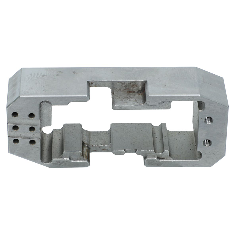
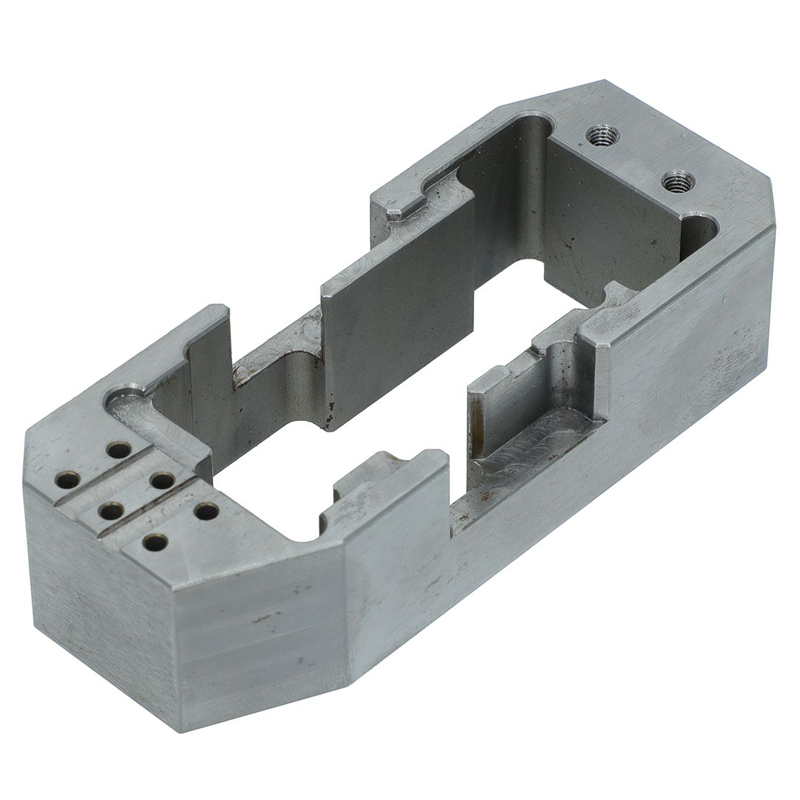
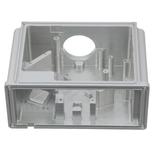
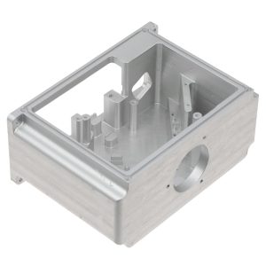
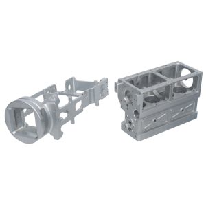
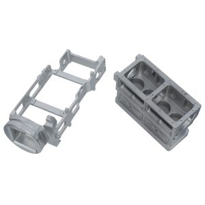
This precision-machined Aluminum Fixture Base (Carrier Jig) is a critical structural component engineered for high-repeatability automated production lines. Featuring a heavily milled, rigid frame with multi-stage locating steps and dedicated mounting interfaces, it serves as the core “skeleton” for automated clamping, testing, and assembly systems. Manufactured via high-speed 3-axis/5-axis CNC milling, this component ensures absolute dimensional stability for delicate workpieces (PCBs, wafers, electronic enclosures) during high-speed robotic handling.
CNC Machining Services Parameters Table
| Parameter | Specification / Capability |
|---|---|
| Product Name | CNC Precision Fixture Base / Positioning Carrier Jig |
| CNC Machining Type | 3-Axis, 4-Axis, 5-Axis CNC Milling (High-Speed) |
| Available Materials | 6061-T6 Aluminum (Standard), 7075-T6 Aluminum, 5052 Aluminum |
| Standard Dimensions | Customized per 2D/3D drawings (Max capacity: 1000mm x 600mm x 400mm) |
| Surface Treatment | Clear/Black Anodizing, Hard Anodizing, Electroless Nickel Plating, Bead Blasting |
| Surface Roughness | Ra 0.8μm to Ra 3.2μm (as machined finish) |
| Geometric Tolerances | Positioning tolerance: ±0.01mm; Flatness: 0.02mm per 100mm |
| General Tolerance | Meets ISO 2768-mK (Fine precision grade) |
| Lead Time (Samples) | 5 – 10 working days (depending on complexity and material availability) |
| MOQ (Minimum Order) | 1 piece (Prototype) / 10-100 pieces (Mass Production) |
| Packaging | Custom foam/plastic box, anti-rust oil, strong export wooden pallet/carton |
Application Scenarios
Because of its highly customizable locating cavities and mounting interfaces, this fixture base is widely deployed in:
-
3C Electronics Automation: Positioning jigs for mobile phone screen assembly, PCB board testing stations, and micro-component soldering fixtures.
-
Semiconductor Equipment: Wafer handling carriers, sensor alignment test bases, and precise sliding platforms.
-
Robotics & End-of-Arm Tooling (EOAT): Mounting bases for robotic grippers and force/torque sensors.
-
General Non-Standard Automation: Custom assembly lines, CNC machine auxiliary tooling, and automatic sorting/feeding tracks.
Material Analysis: Why 6061-T6 Aluminum?
Based on the visible machined surface and structural requirements, this part is preferentially manufactured using 6061-T6 Aluminum Alloy.
-
High Strength-to-Weight Ratio: Provides excellent structural rigidity for high-speed robotic movements while keeping the overall weight low, reducing the load on servo motors.
-
Exceptional Machinability: Allows for deep cavity milling and intricate step profiling without excessive tool wear, resulting in a flawless “as-machined” silver surface finish.
-
Corrosion Resistance: Naturally resistant to oxidation, making it safe for cleanroom environments (Semiconductor/Medical) without coating.
-
Anodizing Compatible: If a black or hard-anodized finish is required, 6061 responds perfectly, providing a wear-resistant and electrically insulating surface.
-
Alternative: For extreme rigidity requirements, we offer 7075-T6 (Aerospace grade) for applications involving high clamping forces.
Precision & Tolerance Capabilities
For a fixture base, the interface surfaces dictate the accuracy of the entire production line. We guarantee the following precision metrics:
-
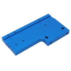
Coordinate Positioning: Critical mounting holes (like the 6-hole array on the left side) are machined with a position tolerance of ±0.01mm to perfectly align with pneumatic cylinders and sensors.
-
Flatness & Parallelism: The bottom base and internal locating steps are held to a flatness of 0.02mm to ensure absolute zero-shift during repetitive clamping cycles.
-
Perpendicularity: The side walls of the interior cavity are milled perpendicular to the base plane within 0.015mm to prevent workpiece tilt.
Manufacturing Challenges & Solutions
This specific geometry presents three significant challenges for CNC machining:
-
Deep Cavity Milling & Tool Deflection:
-
Challenge: The large central void requires long-reach end mills to cut the inner walls and deep steps. Long tools are prone to vibration (chatter), which ruins surface finish.
-
Our Solution: We utilize rigid high-speed spindles, combined with optimized toolpaths (step-over reduction) and special anti-vibration tool holders to maintain a perfect straightness on inner walls.
-
-
Internal Stress Release & Thin-Wall Deformation:
-
Challenge: Removing up to 60% of the material creates severe internal stress in the aluminum block. If heat and stress are not managed, the outer frame will warp.
-
Our Solution: We strictly follow a “Rough machining → Artificial Aging (stress relief) → Semi-finish → Final finish” process to lock the geometric dimensions.
-
-
Multi-Datum Precision:
-
Challenge: The locating steps on the left and right sides must perfectly align with the external bolt holes across different milling operations (flip-flop machining).
-
Our Solution: We utilize 4-axis or 5-axis machining centers to complete multiple faces in a single clamping setup, eliminating accumulated positioning errors.
-
Frequently Asked Questions (FAQ)
Q1: Do you offer prototypes for these custom fixture bases?
A: Absolutely. We have no MOQ for small batches. We specialize in delivering single custom prototypes quickly (usually 5-7 days) to validate your automation design before mass production.
Q2: Can you add threaded holes or tapped holes inside the deep cavity?
A: Yes. Using specialized right-angle milling heads or thread-forming taps on our 5-axis CNC machines, we can precisely tap threads deep inside the cavity exactly as required by your CAD drawing.
Q3: How do you guarantee the positioning accuracy over long-term use?
A: We apply high-precision machining and can perform a hard anodized coating (hardness > 300HV) for the internal locating faces. This increases wear resistance, ensuring the ±0.01mm accuracy lasts for millions of production cycles.
Q4: How should I provide my design files?
A: We accept 2D drawings in PDF/DWG and 3D models in STEP, IGES, or SolidWorks formats. Please include the specific tolerance requirements for critical locating areas.
Q5: What is the standard payment term?
A: For prototypes, we require 100% upfront payment (via TT or PayPal). For mass production, we accept a 30% deposit and 70% balance before shipment.
Additional information
| material |
|---|


Reviews
There are no reviews yet.