
OEM CNC Machined Alloy Steel Linkage Joint Set – H-Type Transfer Bracket & Cylindrical Clevis with Set Screw for Robotic Arms
Description
Unlock Precision Motion Control with Our High-Strength Alloy Steel Linkage Assembly.
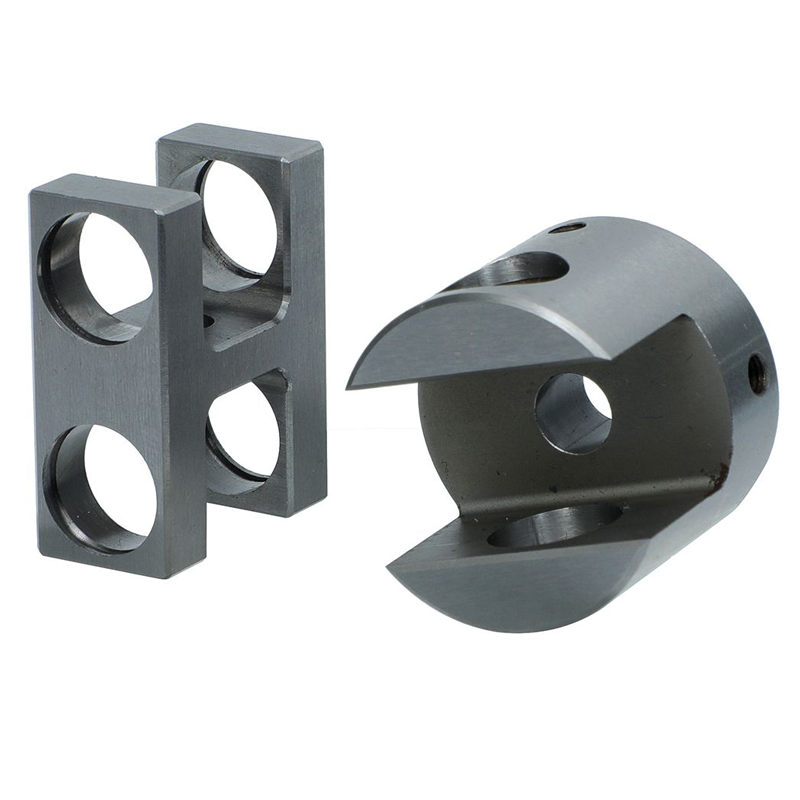
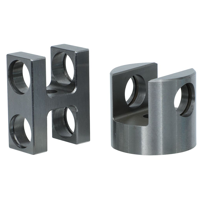
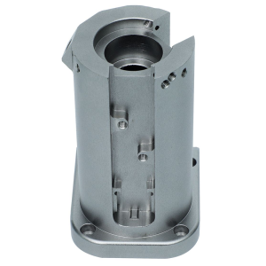
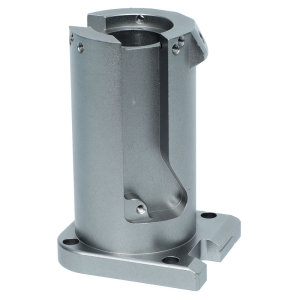
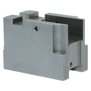
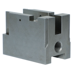
Specifically engineered for heavy-duty industrial automation and robotics, this custom CNC machined linkage joint set comprises a precision H-Type Transfer Bracket and a Cylindrical Clevis Fork with side set-screw locking. Manufactured via advanced CNC turning and milling composites, this steel linkage solution guarantees zero backlash, superior shear strength, and long-term fatigue resistance in high-frequency actuation environments.
CNC Machining Services Specification Table (Parameter Matrix)
We offer fully customizable CNC machining services for this linkage assembly. Below are our standard service capabilities and parameters. Contact us to discuss your specific print.
| Service Parameter | Specification & Capability |
|---|---|
| Available Materials | Alloy Steels (40Cr, 42CrMo, 4140, 4340), Carbon Steel (45#), Stainless Steel (304/316), Tool Steels. |
| Main CNC Processes | CNC Turning (OD/ID), 4-Axis / 5-Axis CNC Milling, Deep Hole Drilling, Precision Boring, Tapping. |
| Surface Finishing | Black Oxide (standard for steel), Electroless Nickel Plating, Phosphating, Hard Chrome Plating, Zinc Plating. |
| Standard Tolerances | ISO 2768-mK (General). Precision fits: H7/H8 clearance fits for pin holes, ±0.01mm positional tolerance. |
| Machinable Size Range | Max Turning Diameter: Ø400mm; Max Milling: 800mm x 600mm x 500mm (Customizable). |
| Surface Roughness (Ra) | Standard Ra 1.6 ~ 3.2. Precision finishing available to Ra 0.8 / Ra 0.4 via precision grinding or fine boring. |
| Quality Inspection | 100% Dimensional Inspection, CMM (Coordinate Measuring Machine) Reports, Hardness Testing, Material Certificates. |
| Lead Time | Prototype: 5-7 working days; Mass Production: 15-25 working days (depending on quantity and finish). |
| MOQ (Minimum Order) | 1-5 pieces for prototype validation; Flexible for mass production. |
In-Depth Material Analysis (Why Alloy Steel?)
Choosing the right material is critical for mechanical linkages. We recommend 40Cr (AISI 5140) or 42CrMo (AISI 4140) for this specific dual-ear assembly:
High Tensile Strength & Yield Strength: These alloy steels offer excellent tensile strength (typically > 800 MPa after heat treatment), allowing the cross-section of the H-type bracket to withstand high pulling and pushing forces without yielding.
Fatigue Resistance: In robotic arms or automated cylinders, this linkage must withstand millions of cyclic movements. Alloy steel exhibits superior fatigue limits compared to standard 45# carbon steel, significantly extending the machine’s service life.
Wear Resistance: The pin holes and inner clamping surfaces undergo localized friction. Alloy steel, when paired with surface hardening (e.g., nitriding or induction hardening prior to CNC finishing), provides outstanding galling resistance.
Precision Tolerance Capabilities
For this linkage joint to function seamlessly, specific dimensional and geometric tolerances must be strictly controlled:
Bore Diameter & Hole Positioning: The transverse pin holes must maintain an H7 tolerance (+0.015~+0.025mm). Our CNC boring and 4-axis milling operations ensure the Coaxiality (concentricity) between the left and right ears of the H-bracket is kept within 0.02mm, preventing angular misalignment that causes joint jamming.
Clevis Slot Width: The U-slot of the cylindrical clevis must mate exactly with the flat sides of the H-bracket. We hold the slot parallelism within 0.015mm to ensure smooth 90° pivoting without binding.
Cylindrical Outer Diameter (OD): The cylindrical clevis must fit precisely into its mounting tube (or actuator rod). Our CNC turning ensures the OD tolerance is maintained to ±0.02mm to guarantee concentricity before the side set screw locks it in place.
Manufacturing Challenges & Our Solutions
This part is not a simple “turn and mill” job; it requires deep process engineering to overcome specific manufacturing hurdles:
Challenge 1: Internal Undercut & Machining of the U-Slot
Difficulty: The U-shape inside the cylindrical clevis requires a thin, long-reach end mill. Reaching deep into the cylinder while avoiding tool deflection is difficult.
Our Solution: We utilize high-stability 5-axis CNC centers combined with specially designed custom toolholders. We employ a high-speed trochoidal milling strategy to minimize cutting forces, ensuring a smooth, surface-finish-spec U-slot without tool marks.Challenge 2: Stress Deformation During Thin-Wall Clamping
Difficulty: Once the U-slot is milled, the cylindrical walls become relatively thin. Standard 3-jaw chucks can deform the roundness during secondary operations.
Our Solution: We use custom soft jaws or hydraulic expansion mandrels to clamp the part on the unfinished OD during final machining. This distributes clamping pressure evenly, ensuring the cylindrical OD remains perfectly round (≤0.005mm circularity) after the machining process.Challenge 3: Eccentricity Between Pin Holes and OD
Difficulty: The transverse pin hole must be perfectly perpendicular (90°) to the OD axis.
Our Solution: We perform the transverse pin hole drilling in a single set-up on a 5-axis machine rather than shifting to a secondary fixture. This eliminates machine-to-machine positioning errors and guarantees true perpendicularity to the cylindrical centerline.
Key Application Scenarios
This custom clevis and bracket linkage assembly is highly versatile. Typical end-uses include:
Robotic End Effectors & Articulated Arms: Used as pivot points at the joints of articulated robotic arms, facilitating multi-axis movement with high torque transfer.
Pneumatic & Hydraulic Cylinder Linkages: Mounted to the rod end of heavy-duty actuators, connecting to levers or sliding mechanisms for swing or push-pull actions.
Automated Packaging & Assembly Lines: Serves as the connecting hinge for cam followers, indexing mechanisms, and high-speed pick-and-place manipulators.
Industrial Linear Motion Systems: Functions as the adapter block connecting the servo motor linear slide to structural machine frames.
Frequently Asked Questions (FAQs)
Q1: What is the difference between your steel clevis and a standard commercial clevis?
A: Standard clevises are often cast or forged with poor hole concentricity. Our CNC-machined alloy steel parts are solid billet cut, ensuring grain flow continuity, vastly superior fatigue life, and strictly controlled hole positioning (±0.01mm) for zero-play pivoting. If you require stainless steel versions for corrosion-sensitive automation environments, check our custom stainless steel CNC machining services.
Q2: Can you customize the set screw location on the cylindrical clevis?
*A: Absolutely. As an OEM CNC machining service, we machine the side set-screw holes and the locking clamp slot exactly as specified in your 2D/3D drawings. We can also add multiple setscrews, counterbores, or custom chamfers.
Q3: How do you ensure the surface of the steel part won’t rust over time?
*A: We offer multiple anti-corrosion solutions. Our standard recommendation is Black Oxide (provides mild oil-retaining rust protection) or Electroless Nickel Plating (ENP) for maximum corrosion resistance (up to 200+ hours of salt spray testing), depending on your working environment.
Q4: Do you offer a certificate of material (MTC) with the order?
*A: Yes. For every steel batch we machine, we provide a 3.1 Material Test Certificate (MTC) according to EN 10204 standards, detailing the chemical composition and mechanical properties of the alloy steel used.
Q5: How does the “H-Type” bracket connect to my robot frame?
*A: The four large through-holes on the “H” bracket allow for cross-axis mounting. You can pass heavy-duty bolts through two vertical holes to attach to a fixed plate, while the other two holes can hold a secondary transverse pin or another threaded rod. We can also create custom custom-length spacing through the central web area.
Ready to get a quote for your custom steel linkage components?
Upload your 2D engineering drawing or 3D STEP file, and our engineering team will provide you with an optimized DFM (Design for Manufacturing) analysis and a competitive quote within 24 hours.
Additional information
| material |
|---|
Reviews
There are no reviews yet.