
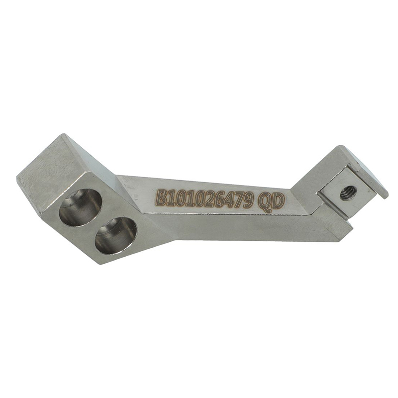
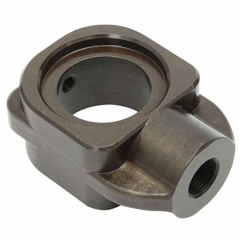
CNC Machined Metal Mounting Block | Custom Precision Machining Part
Description
Product Description
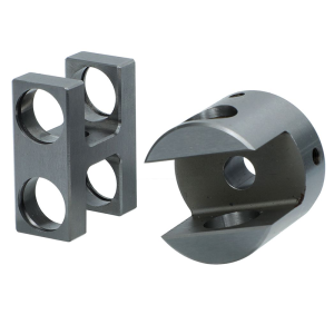
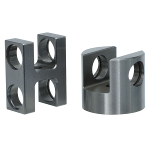
This custom CNC machined metal mounting block is a precision non-standard mechanical component engineered for equipment positioning, assembly mounting and structural support. The part integrates a central stepped through bore, side threaded boss and smooth curved blend radius on transitional surfaces. It is manufactured from solid metal stock via CNC milling, boring, drilling and tapping.
Our team delivers fully OEM custom machining service: you supply drawings or 3D models, we complete DFM analysis, prototype and batch production. This mounting block is built for rigid installation, accurate alignment and stable load bearing without over-specifying part function, suitable for multiple mechanical equipment projects.
CNC Machining Service & Specification Table
表格
| Item | Specification |
|---|---|
| Product Name | CNC Machined Metal Mounting Block |
| Core Machining Operations | CNC Milling, Boring, Drilling, Tapping, Edge Deburring |
| Machine Options | 3-axis CNC / 4-axis index CNC (5-axis simultaneous machining NOT required for this geometry) |
| Size Range | Custom based on customer drawings |
| Standard Dimensional Tolerance | ±0.05 mm (ISO 2768-m) |
| Critical Feature Tolerance | Down to ±0.01 mm upon request |
| Surface Roughness | Ra0.8 ~ Ra3.2 μm |
| Available Raw Materials | Aluminum Alloy (6061-T6 /7075), Carbon Steel, Alloy Steel, Stainless Steel (304 /316L), Brass, Copper |
| Available Surface Treatment | Hard Anodizing, Black Oxide, Sandblasting, Passivation, Powder Coating |
| Inspection | First article inspection, in-process QC, final dimensional check; CMM inspection optional |
| File Acceptance | STEP, IGES, Solidworks, PDF 2D drawing |
| Lead Time | Prototype: 3–7 days; Mass production: 7–20 days |
Material Selection & Material Analysis
We support multiple metal substrate options for this custom mounting block, selected according to your load requirement, weight target and working environment:
- Aluminum Alloy (6061-T6 /7075) Lightweight, good machinability, excellent corrosion resistance after hard anodizing. Ideal for automation equipment, low-to-medium load positioning structures. It reduces total assembly weight while retaining enough rigidity.
- Carbon Steel / Alloy Steel (45#, 40Cr) Higher tensile strength and wear resistance. Best choice for heavy-load mounting positions; black oxide surface treatment provides basic rust protection.
- 304 / 316L Stainless Steel Strong corrosion resistance for wet, chemical or outdoor environments. Slightly higher machining cost and tool wear.
- Brass / Copper Good anti-friction performance, suitable for low-load assembly requiring electrical conductivity.
Recommendation: Confirm working load, temperature and environment before finalizing material grade. Our engineer can give material suggestions during DFM review.
Application Scenarios
This CNC machined metal mounting block serves as a positioning and mounting base widely used across industrial sectors:
- Industrial automation equipment, fixture & tooling assemblies
- General machinery and mechanical module mounting
- Robot auxiliary structure & equipment sub-frame positioning
- Custom test jigs, instrumentation housing supports
- OEM mechanical assemblies for automated production lines
Note: This is a universal custom mounting component. It can be adapted to different assemblies, we do not predefine it as bearing housing, steering knuckle or hydraulic valve body without your drawing confirmation.
Tolerance Capability
Our default tolerance follows ISO 2768-m standard.
- General non-critical dimensions: ±0.05 mm
- Precision features (bore, threaded hole position, mating surfaces): Tight tolerance down to ±0.01 mm available
- Position & form tolerances (positionality, flatness, perpendicularity): Customizable as your drawing requirement
- Thread: Metric / UNC / UNF threads, thread gauge inspection available
Tight tolerance requests will be reviewed via DFM. Some ultra-tight tolerance requirements may increase fixture cost and lead time.
Manufacturing Difficulties
- Orthogonal multi-direction feature alignment Central stepped bore and side threaded boss are perpendicular. The position 度 between side thread hole and central bore needs strict fixture control. Using 4-axis single-setup machining eliminates cumulative error caused by repeated re-clamping.
- Smooth curved blend radius machining Continuous transitional curved surface requires ball-end cutter contour milling. Tool path optimization is required to avoid visible tool marks and ensure smooth transition.
- Deburring on internal corners and thread edges Sharp burrs at hole intersections and curved transition zones must be fully removed to prevent assembly scratching and stress concentration. Manual or vibratory deburring is applied.
- Consistency in batch production Fixture repeatability and periodic tool wear monitoring are required to guarantee identical hole position and contour geometry across batches.
FAQ
Q1: Is 5-axis machining required for this mounting block?
A: 5-axis simultaneous machining is NOT required. The part’s orthogonal holes and blend radius can be completed by 3-axis multi-setup or 4-axis indexing milling. We recommend 4-axis processing when tight position tolerance is required. This helps you save machining cost.
Q2: Can I get prototype samples before mass order?
A: Yes. We support one-off prototype and small batch pre-production samples. Send your 2D/3D drawings for DFM review and quotation.
Q3: What file formats do you accept for custom CNC machining?
A: We accept STEP, IGES, SolidWorks SLDPRT, PDF engineering drawings. 2D drawing with dimension and tolerance notes is mandatory for formal inspection.
Q4: What surface finishes can you apply?
A: Hard anodizing, black oxide, sandblasting, passivation, powder coating. Finish selection depends on material, wear and corrosion requirements.
Q5: Can you inspect parts with CMM?
A: Yes, CMM 3D inspection service is available for critical dimension verification, extra cost applies.
Q6: What if I do not have 3D files?
A: You can provide 2D engineering drawings, hand sketches or physical samples. Our engineering team can create 3D models for you (extra modeling service may apply).
Additional information
| material |
|---|
Reviews
There are no reviews yet.