
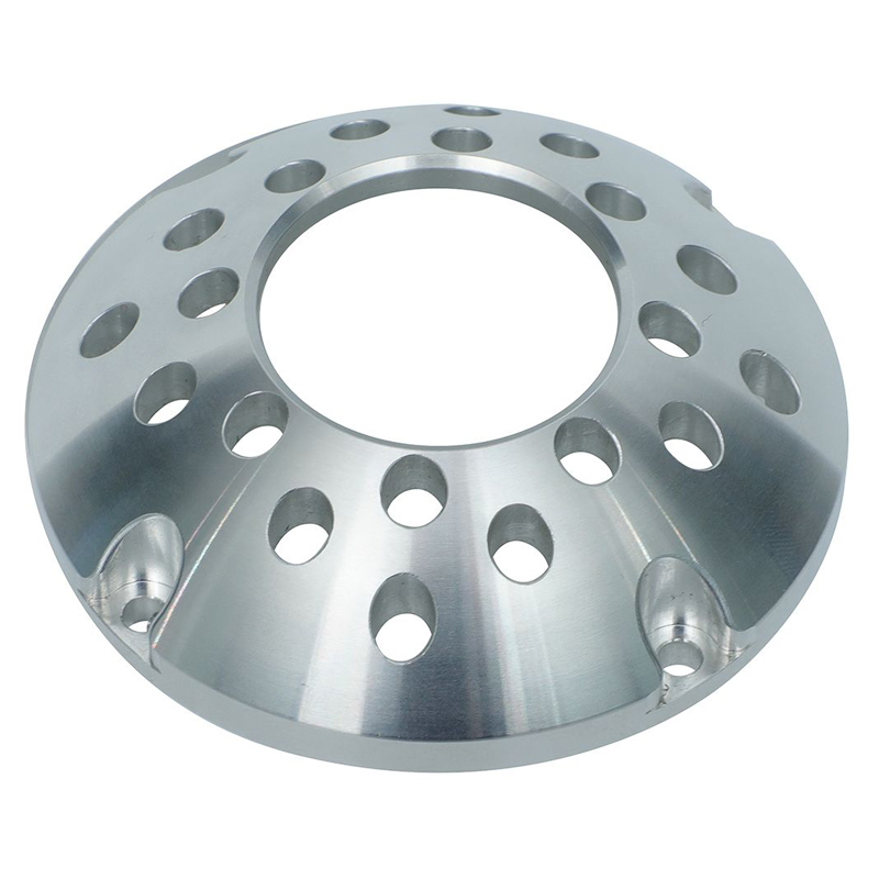
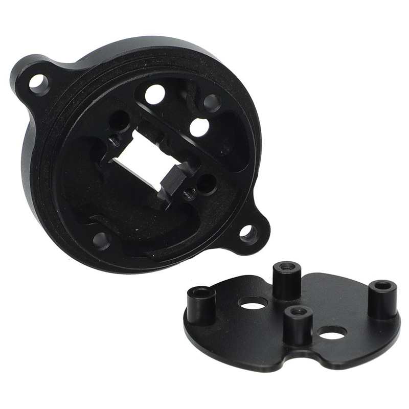
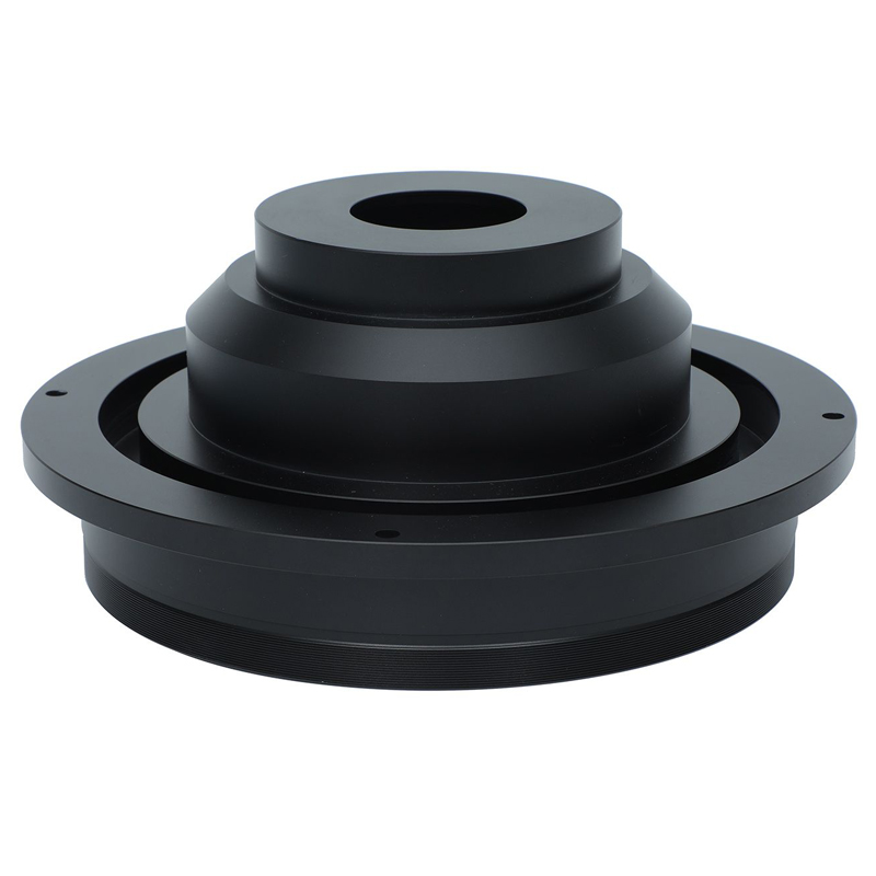
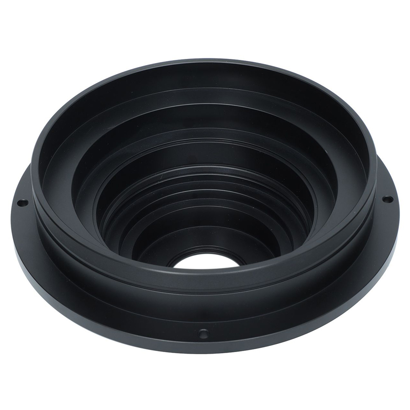
Custom CNC Machined Flanged Optical Lens Barrel with Multi-Step Internal Bores
Description
Product Overview
A flanged optical lens barrel is a precision-machined cylindrical housing that holds and aligns multiple optical elements — lenses, spacers, and aperture stops — along a single optical axis. Our CNC machined lens barrels with multi-step internal bores are manufactured from high-grade aluminum alloys and finished with black anodizing to suppress internal stray light, making them ideal for demanding imaging and photonics applications.
Each internal step is precision-bored to locate a specific lens element, controlling both radial position (concentricity) and axial spacing (air gap) with micron-level accuracy. The integrated mounting flange provides a rigid, repeatable interface to camera bodies, lens turrets, or optical benches.
Why manufacturers choose our lens barrels: Single-setup CNC turning guarantees bore-to-flange concentricity down to ±0.005 mm, and black anodizing delivers ≤ 5% reflectance across visible and near-IR wavelengths — critical for high-contrast imaging.
CNC Machining Services & Specifications
| Parameter | Specification |
|---|---|
| Product Name | Flanged Optical Lens Barrel with Multi-Step Internal Bores |
| Manufacturing Process | CNC Turning (Lathe) + CNC Milling (flange holes) + Deburring |
| Material Options | Aluminum 6061-T6, Aluminum 7075-T6, Aluminum 5052, Brass C36000, Stainless Steel 304/316, Titanium Grade 5 |
| Standard Material | Aluminum 6061-T6 (black anodized) |
| Outer Diameter (OD) Range | Ø10 mm – Ø300 mm (custom sizes available) |
| Inner Diameter (ID) Range | Ø3 mm – Ø280 mm |
| Length / Height Range | 5 mm – 300 mm |
| Number of Internal Bore Steps | 2 – 12 steps (custom step profiles) |
| Flange Type | Integrated circular flange, square flange, or custom profile |
| Mounting Holes | 2 – 12 through-holes or tapped holes; standard M2/M2.5/M3/M4/M5/M6 |
| Thread Options | C-mount (1″-32 UN), CS-mount, M12×0.5, M25×0.5, M30×0.75, custom threads |
| General Tolerance (ISO 2768-m) | ±0.05 mm (linear), ±0.5° (angular) |
| Precision Tolerance | ±0.005 mm – ±0.01 mm (bore diameter), ±0.01 mm (axial step depth) |
| Concentricity (Bore-to-Flange) | ≤ 0.005 mm (TIR) — single-setup turning |
| Surface Finish (Internal Bores) | Ra 0.4 μm – Ra 0.8 μm (16–32 μin) as standard; Ra 0.2 μm (8 μin) on request |
| Surface Finish (External) | Ra 0.8 μm – Ra 1.6 μm (32–63 μin) |
| Surface Treatment | Black Anodizing (Type II / Type III Hard Anodize), Clear Anodizing, Chromate Conversion, Electroless Nickel, Passivation |
| Black Anodize Reflectance | ≤ 5% (visible spectrum, 400–700 nm) |
| Certifications | ISO 9001:2015, RoHS compliant, REACH compliant |
| Inspection Equipment | CMM, Optical Comparator, Surface Roughness Tester, Pin Gauges, Bore Gauges, Height Gauge |
| MOQ | 1 piece (prototyping) — high-volume production supported |
| Lead Time (Prototype) | 5 – 7 working days |
| Lead Time (Production) | 15 – 25 working days (depending on quantity) |
| Drawing Format | STEP, IGES, DWG, DXF, PDF, SolidWorks (.sldprt) |
Applications
Our flanged optical lens barrels serve across industries where precise optical alignment and stray-light control are non-negotiable:
Industrial Machine Vision
- Factory automation cameras — lens housings for inspection systems on production lines
- 2D/3D vision sensors — barrels for structured-light and time-of-flight optics
- Barcode and QR code readers — compact lens tubes with integrated mounting flanges
Professional Photography & Cinema
- Interchangeable camera lenses — multi-element lens barrels for prime and zoom lenses
- Cinema lens housings — high-precision barrels with focus/iris gear interfaces
- Anamorphic lens components — stepped bores for cylindrical lens stacks
Life Sciences & Medical Imaging
- Microscope objectives — multi-step barrels for achromatic and apochromatic lens groups
- Endoscope lens assemblies — miniature diameter lens tubes for rigid endoscopes
- Ophthalmic equipment — lens housings for fundus cameras and slit lamps
Laser & Photonics
- Laser beam expanders — stepped bores for Galilean and Keplerian expander lenses
- Collimator housings — precision barrels for fiber-optic collimators
- Spectrometer optics — lens tubes for monochromators and spectrographs
Aerospace & Defense
- Targeting and surveillance optics — ruggedized lens barrels for military-grade systems
- Satellite imaging components — lightweight aluminum housings for space-borne cameras
- Thermal imaging lenses — barrels for IR optical assemblies (germanium lens compatible)
Material Analysis
The choice of material directly impacts optical stability, thermal performance, weight, and cost. Learn more about core principles behind material selection for optical enclosures in our guide: CNC Machining of Optical Enclosures: How to Select Materials to Ensure Optical Performance. Below is a comparative analysis of the most commonly specified materials for flanged lens barrels:
Aluminum 6061-T6 — The Standard Choice
| Property | Value | Relevance to Lens Barrels |
|---|---|---|
| Density | 2.70 g/cm³ | Lightweight — reduces load on camera mounts and gimbals |
| Thermal Conductivity | 167 W/(m·K) | Efficient heat dissipation — prevents thermal focal shift |
| Coefficient of Thermal Expansion (CTE) | 23.6 × 10⁻⁶ /°C | Matches common optical glass (BK7 CTE ≈ 7.1 × 10⁻⁶) with compliant mounting |
| Tensile Strength | 310 MPa | Sufficient rigidity for most lens barrel applications |
| Machinability | Excellent | Produces fine surface finishes on internal bores |
| Anodizing Compatibility | Excellent | Black anodize Type II/III delivers low reflectance |
| Cost | Low | Most economical option for prototyping and production |
Best for: General-purpose industrial lenses, machine vision, consumer cameras.
Aluminum 7075-T6 — High-Strength Upgrade
| Property | Value | Relevance |
|---|---|---|
| Density | 2.81 g/cm³ | Slightly heavier than 6061 |
| Tensile Strength | 572 MPa | 85% stronger — ideal for thin-wall and high-vibration environments |
| CTE | 23.4 × 10⁻⁶ /°C | Similar to 6061 |
| Machinability | Good | Slightly more abrasive than 6061; requires sharp tooling |
| Anodizing | Good | Accepts black anodize well; slightly more porosity than 6061 |
| Cost | Medium-High | 2–3× the material cost of 6061 |
Best for: Aerospace and defense optics, high-G environments, large-format lenses requiring structural rigidity.
Brass C36000 — For Miniature Precision
| Property | Value | Relevance |
|---|---|---|
| Density | 8.53 g/cm³ | High mass — provides thermal stability and damping |
| Machinability | Excellent (best among common alloys) | Achieves ultra-fine surface finishes (Ra 0.2 μm) on tiny bores |
| CTE | 20.5 × 10⁻⁶ /°C | Closer to optical glass than aluminum |
| Surface Treatment | Nickel plating, black oxide | Black nickel plating provides stray-light suppression |
| Cost | Medium | Higher material cost, offset by superior machinability |
Best for: Endoscope lens tubes, miniature microscope objectives, small-format high-precision lenses.
Stainless Steel 304/316 — For Harsh Environments
| Property | Value | Relevance |
|---|---|---|
| Density | 7.93 / 7.98 g/cm³ | Heavy — not ideal for weight-sensitive applications |
| Corrosion Resistance | Excellent (316 > 304) | Withstands salt spray, chemicals, sterilization (autoclave) |
| Machinability | Fair | Work-hardens; requires rigid setup and sharp carbide tooling |
| Surface Treatment | Passivation, electropolishing, PVD black coating | PVD DLC (Diamond-Like Carbon) for low-reflectance black finish |
| Cost | High | Higher material and machining cost |
Best for: Medical endoscopes (autoclave-compatible), marine optics, chemical processing imaging.
Material Selection Decision Matrix
| Application Priority | Recommended Material |
|---|---|
| Cost optimization + general performance | Aluminum 6061-T6 |
| High strength / vibration resistance | Aluminum 7075-T6 |
| Ultra-small diameter (< Ø10 mm) + fine finish | Brass C36000 |
| Corrosion resistance / sterilization | Stainless Steel 316L |
| Weight reduction + biocompatibility | Titanium Grade 5 |
Tolerance Capabilities
Optical lens barrels demand some of the tightest tolerances in CNC machining. A single micron of misalignment can degrade image resolution, introduce astigmatism, or shift focal plane. Our capabilities are calibrated to meet these requirements:
Dimensional Tolerances
| Feature | Standard Capability | Precision Capability | Ultra-Precision (On Request) |
|---|---|---|---|
| Bore Diameter (ID) | ±0.01 mm | ±0.005 mm | ±0.002 mm |
| Outer Diameter (OD) | ±0.01 mm | ±0.005 mm | ±0.002 mm |
| Step Depth (Axial) | ±0.01 mm | ±0.005 mm | ±0.002 mm |
| Flange Thickness | ±0.02 mm | ±0.01 mm | ±0.005 mm |
| Hole Position (Flange) | ±0.02 mm | ±0.01 mm | ±0.005 mm |
| Thread Pitch Diameter | 6H / 6g (ISO) | 4H / 4g (ISO) | Custom |
Geometric Tolerances (GD&T)
| Characteristic | Symbol | Standard | Precision | Ultra-Precision |
|---|---|---|---|---|
| Concentricity (all bores to axis) | ◎ | 0.01 mm TIR | 0.005 mm TIR | 0.002 mm TIR |
| Perpendicularity (flange face to bore axis) | ⟂ | 0.01 mm | 0.005 mm | 0.002 mm |
| Cylindricity (bore walls) | ⌭ | 0.005 mm | 0.003 mm | 0.001 mm |
| Flatness (flange mounting face) | ▱ | 0.01 mm | 0.005 mm | 0.002 mm |
| Parallelism (opposite flange faces) | ∥ | 0.01 mm | 0.005 mm | 0.002 mm |
| Runout (OD to ID) | ↗ | 0.01 mm | 0.005 mm | 0.002 mm |
| Position (mounting holes to axis) | ⌖ | 0.02 mm | 0.01 mm | 0.005 mm |
Surface Finish Capabilities
| Surface | Standard | Precision | Ultra-Precision |
|---|---|---|---|
| Internal bore (lens contact) | Ra 0.8 μm (32 μin) | Ra 0.4 μm (16 μin) | Ra 0.1 μm (4 μin) / polished |
| Internal bore (non-contact) | Ra 1.6 μm (63 μin) | Ra 0.8 μm (32 μin) | Ra 0.4 μm (16 μin) |
| External cylindrical | Ra 1.6 μm (63 μin) | Ra 0.8 μm (32 μin) | Ra 0.4 μm (16 μin) |
| Flange mounting face | Ra 1.6 μm (63 μin) | Ra 0.8 μm (32 μin) | Ra 0.4 μm (16 μin) |
Critical note: Surface finish on lens-seating bores directly affects lens centration. A rough bore surface can cause a lens element to tilt by several arc-minutes. We recommend Ra ≤ 0.4 μm on all lens-locating diameters.
Inspection & Verification
Every lens barrel undergoes inspection using:
- Coordinate Measuring Machine (CMM) — for 3D dimensional and geometric verification
- Bore Gauges / Internal Micrometers — for bore diameter measurement to ±0.001 mm
- Pin Gauge Sets (Class X) — for go/no-go verification of critical bores
- Optical Comparator / Vision System — for profile and thread inspection
- Surface Roughness Tester (Profilometer) — for Ra/Rz verification on all critical surfaces
- Dial Indicator on V-Block — for concentricity and runout verification (TIR)
- Height Gauge — for step depth and flange thickness verification
First Article Inspection (FAI) reports are available upon request, conforming to AS9102 / PPAP standards.
Manufacturing Challenges & Solutions
Producing a multi-step flanged lens barrel to optical-grade precision involves several inherent manufacturing challenges. Here is how we address each:
Challenge 1: Maintaining Concentricity Across Multiple Bore Steps
The problem: Each internal bore step must share the same central axis. Even a 5 μm offset between adjacent steps causes lens decenter, resulting in coma and reduced MTF (Modulation Transfer Function). Conventional machining — turning one end, then flipping the part — introduces cumulative error from re-chucking.
Our solution:
- Single-setup turning — all internal bores and the outer diameter are machined in one clamping operation on a high-precision CNC lathe with a sub-spindle, eliminating re-chucking error
- Collet chucking on the OD rather than 3-jaw chuck, reducing clamping-induced eccentricity to < 2 μm
- Finishing pass at low feed rate (0.05 mm/rev) with sharp diamond-tipped or carbide inserts to minimize tool deflection
- In-process gauging — bore diameter measured after each roughing pass to compensate for tool wear before the finishing pass
Result: Concentricity ≤ 0.005 mm TIR across all bore steps, verified by CMM and indicator runout.
Challenge 2: Achieving Fine Surface Finish on Deep, Small-Diameter Internal Bores
The problem: Deep internal bores (length-to-diameter ratio > 3:1) suffer from tool chatter, poor chip evacuation, and limited coolant access — all of which degrade surface finish. A rough bore surface scatters light and can physically damage delicate lens edges during assembly.
Our solution:
- Boring bars with internal coolant-through — delivers high-pressure coolant (70 bar) directly to the cutting edge, improving chip evacuation and reducing heat-induced tool wear
- Anti-vibration boring bars (tungsten carbide shank with tuned damping) for L/D ratios up to 8:1, suppressing chatter
- Two-stage boring — rough boring leaves 0.15–0.20 mm stock; finish boring at reduced depth of cut (0.05–0.10 mm) and optimized spindle speed
- Honing or roller burnishing as a post-process for ultra-precision applications, achieving Ra ≤ 0.1 μm
- Chip-breaking inserts with controlled chip geometry to prevent stringy chips from marring the finished bore surface
Result: Internal bore surface finish consistently Ra 0.4–0.8 μm, with Ra 0.2 μm achievable on request.
Challenge 3: Black Anodizing Uniformity on Complex Internal Geometries
The problem: Black anodizing requires uniform current distribution across all surfaces. In deep, multi-step bores, the “throwing power” of the anodizing bath is reduced — inner steps may receive a thinner, lighter-colored oxide layer, increasing reflectance and creating cosmetic inconsistency.
Our solution:
- Type II sulfuric acid anodizing with optimized bath temperature (20±2°C) and current density (1.2–1.5 A/dm²) for uniform coating
- Acid zincating pre-treatment to ensure uniform oxide nucleation across the aluminum surface
- Dual-tank process — degrease → etch → desmut → anodize → dye (black, organic dye #40) → seal (nickel acetate hot seal)
- Custom fixturing with auxiliary cathodes placed inside the bore to improve current distribution on deep internal surfaces
- Coating thickness control at 10–15 μm (Type II) or 25–50 μm (Type III hard anodize) with verified uniformity across all steps
- Reflectance verification using a spectrophotometer on sample coupons processed alongside production parts
Result: Uniform black anodize with ≤ 5% reflectance (visible spectrum) across all internal bore surfaces, including the deepest steps.
Challenge 4: Controlling Thermal Expansion During Machining
The problem: Aluminum has a high CTE (23.6 × 10⁻⁶ /°C). During machining, cutting heat can raise the part temperature by 5–15°C, causing the bore to expand by 5–20 μm. If measured while hot, the part will be out of tolerance when it cools to room temperature (20°C).
Our solution:
- Flood coolant at controlled temperature (20±1°C) — maintains thermal stability of both part and machine tool during cutting
- Thermal soak before measurement — parts are allowed to stabilize at 20°C for a minimum of 2 hours before final inspection
- Climate-controlled inspection room (20±1°C, 45–55% RH) for all precision measurement
- Compensated machining — for ultra-precision parts, in-process gauging accounts for current part temperature and applies CTE compensation to the final pass
- Minimal heat generation — using sharp tooling, appropriate feeds/speeds, and climb milling to reduce cutting heat
Result: Dimensional accuracy verified at standard reference temperature (20°C), with full CTE compensation documented for critical dimensions.
Challenge 5: Flange Hole Position Accuracy Relative to Bore Axis
The problem: Mounting holes in the flange must be precisely positioned relative to the central bore axis to ensure the lens barrel mounts coaxial to the camera sensor. Milling holes on a separate operation introduces datum shift.
Our solution:
- Turn-mill center (live tooling lathe) — flange holes are drilled and tapped on the same machine, same setup as the turning operation, using the bore axis as the reference datum
- Indexing accuracy of the C-axis (sub-arc-second resolution) ensures angular positioning of holes to ±0.01 mm at the pitch circle
- Spot drill → pilot drill → final drill → ream sequence for through-holes, ensuring hole straightness and diameter consistency
- Coordinate verification on CMM, measuring each hole’s position relative to the bore axis (established by probing the internal bore)
Result: Flange hole position accuracy ≤ 0.01 mm relative to bore axis, with angular indexing error < 5 arc-minutes.
Challenge 6: Deburring Internal Step Edges Without Affecting Critical Dimensions
The problem: Each internal bore step creates a sharp 90° edge (the lens-seating shoulder). Machining leaves micro-burrs on these edges that can prevent a lens from seating flat, causing tilt. Manual deburring with abrasive tools can easily remove 0.01–0.05 mm from the critical shoulder diameter or depth.
Our solution:
- Sharp-tool finishing pass — the final boring pass uses a freshly honed insert with a sharp edge (hone < 0.02 mm), producing minimal burr formation
- Controlled chamfering — non-critical internal edges receive a programmed 0.1–0.2 mm × 45° chamfer during machining, eliminating the need for manual deburring
- Cryogenic deburring or tumbling with ceramic media for batch processing — removes micro-burrs without affecting critical dimensions (media size and hardness controlled)
- Hand deburring only on non-critical external edges — performed by skilled operators with magnification, using precision carbide scrapers
- 100% visual inspection under 10× magnification for burr-free verification on all lens-seating surfaces
Result: All lens-seating shoulders are burr-free with sharp, clean edges, verified under magnification. Critical dimensions unaffected by deburring.
Frequently Asked Questions (FAQ)
Q1: What is the minimum order quantity (MOQ) for a custom lens barrel?
A: We accept orders starting from 1 piece for prototyping and R&D purposes. For production volumes, we typically recommend batches of 50+ pieces to optimize per-unit cost. There is no hard MOQ — we support everything from one-off prototypes to high-volume production runs of 10,000+ pieces per year.
Q2: Can you manufacture lens barrels from my optical design / lens prescription?
A: Yes. If you provide the optical prescription (lens element diameters, thicknesses, air gaps, and mechanical envelope), our engineering team can design the lens barrel mechanical layout — including step diameters, step depths, retaining thread specifications, and flange dimensions. We can also work from your existing STEP/IGES/DWG files for direct manufacturing.
Q3: What is the typical lead time for a prototype lens barrel?
A: Standard prototype lead time is 5–7 working days from drawing approval for aluminum parts with black anodizing. If additional processes are required (such as thread chasing, special coatings, or ultra-precision honing), lead time may extend to 10–14 working days. Rush service (3–5 days) is available for an additional fee — please inquire.
Q4: How do you ensure the black anodizing does not affect critical bore dimensions?
A: Black anodizing (Type II) adds approximately 5–8 μm of oxide layer per surface (half penetrates into the aluminum, half builds up). We account for this in our machining by leaving anodizing allowance on all critical dimensions — typically 0.01–0.015 mm per surface. After anodizing, the dimensions fall within the specified tolerance. For ultra-precision parts, we can also perform post-anodize honing to bring critical bores to final dimension. All anodizing allowances are documented on the manufacturing drawing.
Q5: Can you produce lens barrels with internal threads for lens retaining rings?
A: Yes. We can machine internal threads for lens retaining rings (lock rings) in a variety of standards and custom specifications. Common thread forms include:
- Metric fine threads: M16×0.5, M20×0.5, M25×0.5, M30×0.75, M35×0.75, M42×0.75
- UN threads: 1″-32 (C-mount), 1.035″-40, 1.5″-32
- Custom threads per your specification
Threads are chased with single-point tooling on the CNC lathe for accurate pitch diameter and concentricity to the bore axis. Thread quality is verified with thread ring gauges / plug gauges and optical comparators.
Q6: What is the maximum length-to-diameter (L/D) ratio you can achieve for internal bores?
A: With standard carbide boring bars, we achieve L/D ratios up to 5:1 with excellent surface finish and concentricity. Using tungsten carbide anti-vibration boring bars with through-coolant, we extend this to 8:1. For extreme L/D ratios (up to 12:1), we use gun boring or BTA (Boring and Trepanning Association) deep-hole drilling followed by reaming. Please note that surface finish and tolerance may need to be relaxed for L/D ratios exceeding 8:1 — our engineering team will advise on achievable specifications for your specific geometry.
Q7: Do you provide assembly services (pressing lenses, installing retaining rings)?
A: We primarily manufacture the lens barrel mechanical components. However, for select customers, we offer sub-assembly services including:
- Installation of lens spacers and retaining rings
- Press-fit or shrink-fit assembly of lens elements (with optical alignment verification)
- Installation of set screws and alignment pins
- Cleanroom assembly (Class 1000 / ISO 6) for optical components
Please note that optical element installation and active alignment require specialized equipment and are evaluated on a case-by-case basis. We are happy to discuss your assembly requirements during the quote phase.
Q8: How do you package lens barrels to prevent damage during shipping?
A: Each lens barrel is individually packaged to protect critical surfaces:
- Cleaning — parts are ultrasonically cleaned and dried to remove machining coolant and debris
- Surface protection — critical bore surfaces are covered with protective caps or foam plugs; flange faces are protected with adhesive film
- Individual wrapping — each part is wrapped in anti-static, lint-free foam or bubble wrap
- Boxing — parts are placed in rigid cardboard boxes with foam inserts, with sufficient padding to prevent movement during transit
- Labeling — each box is labeled with part number, quantity, and “Fragile — Precision Optical Components” handling instructions
For international shipping, we use DHL, FedEx, or UPS with full tracking and insurance. Custom packaging (ESD bags, cleanroom packaging, vacuum-sealed) is available on request.
Q9: Can you meet ITAR / EAR requirements for defense-related lens barrels?
A: We are experienced in manufacturing optical components for defense and aerospace applications. We can comply with ITAR (International Traffic in Arms Regulations) and EAR (Export Administration Regulations) requirements, including:
- Secure facility access controls
- Restricted access to technical data (no cloud storage, encrypted communications)
- Certificate of conformance with country-of-origin documentation
- No foreign national access to controlled technical data
- Destruction of manufacturing data upon project completion (if required)
Please disclose any ITAR/EAR classification during the initial inquiry so we can ensure proper handling and compliance. Note that we do not manufacture items on the US Munitions List (USML) without proper licensing.
Q10: What file formats do you accept for drawings, and can you sign NDAs?
A: We accept all standard CAD formats:
- 3D models: STEP (.stp/.step), IGES (.igs/.iges), SolidWorks (.sldprt), CATIA (.CATPart), Creo/ProE (.prt), Inventor (.ipt)
- 2D drawings: DWG, DXF, PDF (with dimensioned tolerances)
We routinely sign Non-Disclosure Agreements (NDAs) before receiving sensitive technical data. Our standard NDA is mutual (protecting both parties), and we are happy to review and sign your company’s NDA template. All technical data is stored on secure, access-controlled servers with encrypted backups.
Q11: How do you handle dimensional inspection reporting for critical parts?
A: For all lens barrel orders, we provide:
- Material certification (mill test report / certificate of conformance) verifying alloy and temper
- Anodizing certification verifying coating type, thickness, and seal quality
- Dimensional inspection report — full layout inspection on the first article (FAI), with sampling inspection (AQL 1.0 / 2.5) on production lots
- CMM reports with graphical deviation maps for critical geometric tolerances (concentricity, perpendicularity)
- Surface finish readings (Ra/Rz) for all critical surfaces
- PPAP Level 3 documentation available for automotive and medical customers upon request
All inspection data is traceable to calibrated equipment (calibration certificates available on request).
Q12: Can you produce lens barrels with non-circular internal bores or custom step profiles?
A: Yes. While most lens barrels use circular stepped bores, we can manufacture custom internal profiles including:
- Tapered / conical bores (for certain lens mounting schemes)
- Keyways or flats inside bores (for anti-rotation of lens cells)
- Non-circular (D-shaped, square, hexagonal) bores using CNC milling with boring head or EDM
- Custom step profiles with chamfers, radii, or undercuts at specific locations
- Helical internal grooves (for focus helicoids in zoom lenses)
Non-standard internal geometries may require additional machining operations (EDM, 5-axis milling) and may affect achievable tolerances and lead time. Our engineering team will review your geometry and provide a manufacturability assessment with the quote.
Additional information
| material |
|---|

Reviews
There are no reviews yet.