
Custom CNC Machined Robotics Mounting Base Assembly with Integrated Standoff Plate
Description
Product Overview
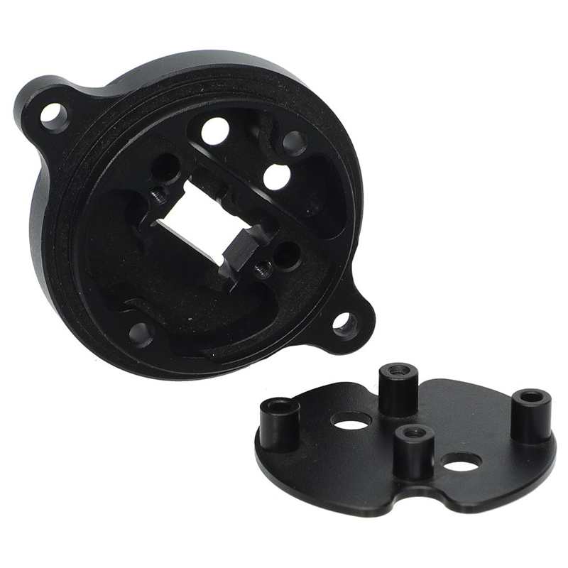
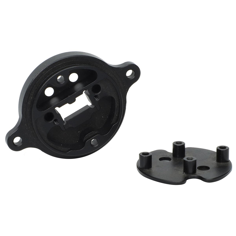
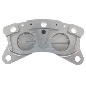
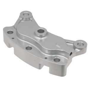
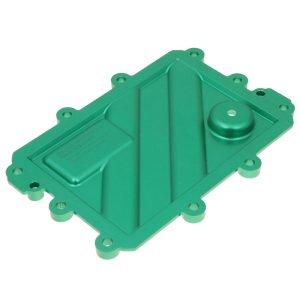
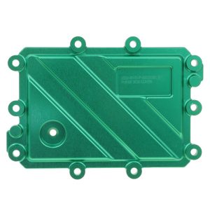
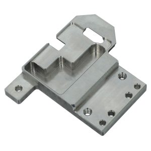
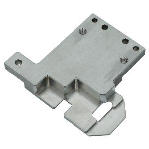
This custom CNC-machined robotics mounting base assembly consists of one main housing cover plate and one locating standoff base plate. Designed for modular mechanical assembly, the large housing cover features external mounting lugs and complex internal contoured cavities to accommodate sensors, PCBs, and compact actuator sub-components.
The matched standoff base plate comes with integral threaded locating bosses, providing precise positioning, internal component support, and secure screw fastening points.
Manufactured by multi-axis CNC milling via our 5 Axis CNC Machining Services , the assembly is finished with black hard anodizing for wear resistance, corrosion protection, and a consistent surface appearance. It is a typical custom mechanical sub-assembly for robotics and mechatronic equipment rather than an off-the-shelf standard part.
Every dimension and feature can be customized according to customer drawings or 3D STEP files. See our custom robot parts manufacturing for additional robotics CNC machining capabilities.
CNC Machining Services Specification Table
| Item | Specification Details |
|---|---|
| Product Name | Custom CNC Machined Robotics Mounting Base Assembly with Integrated Standoff Plate |
| Component Parts | 1 × Housing Cover Plate, 1 × Locating Standoff Base Plate |
| Available Processes | 5-Axis CNC Milling, 3-Axis CNC Milling, Tapping, Deburring |
| Common Material Options | 6061-T6 Aluminum, 6063 Aluminum, 7075-T6 Aluminum, 303 / 304 Stainless Steel |
| Surface Finishes | Black Hard Anodizing, Clear Anodizing, Sandblasting, Passivation (Stainless Steel) |
| Part Max. Dimension | ≤300 mm (Customizable) |
| Minimum Wall Thickness | 0.8 mm |
| Standard Tolerance | ±0.02 mm; tight tolerance down to ±0.005 mm upon request |
| Surface Roughness | Ra 0.8 μm–Ra 3.2 μm |
| Acceptable Input Files | STEP, STP, IGES, SolidWorks, PDF Engineering Drawings |
| Lead Time | Prototype: 7–10 working days; Mass Production: 15–25 working days |
| QC Control | CMM Inspection, Micrometer Measurement, Thread Gauge Check, Visual Surface Inspection |
Application Scenarios
This mounting base assembly is engineered for compact modular mechanical systems. Typical application fields include:
1. Humanoid Robot Sub-Modules
Used for joint auxiliary positioning, sensor module housings, and internal electronic component mounting.
2. Service & Warehouse Robots
Suitable for AGV sensor mounting bases, compact actuator enclosures, and internal PCB support assemblies.
3. Industrial Automation Equipment
Used in inspection detection module housings, pick-and-place auxiliary positioning assemblies, and motion-unit sub-frames.
4. Electromechanical Sensor Modules
Provides enclosure and locating support for optical sensors, proximity sensors, and compact control electronics.
5. Custom Test & Instrument Equipment
Suitable for custom fixture housings used in laboratory testing devices and small-scale measuring instruments.
Note: This assembly is a general-purpose custom mechanical sub-assembly. Without additional design or application evidence, it cannot be exclusively classified as an automotive, medical, or optical-specific end-product component.
Material Analysis
6061-T6 Aluminum — Most Selected for This Assembly Type
Advantages:
Excellent CNC machinability, good strength-to-weight ratio, and stable anodizing performance. Black anodizing can improve surface wear resistance and provide electrical insulation. It is also generally more economical than 7075-T6 aluminum.
Limitations:
Not the preferred choice for extremely high-load structural applications where maximum strength is required.
Typical Fit:
Robotics sensor mounts, electronic mounting assemblies, actuator support components, and general-purpose automation structures.
7075-T6 Aluminum
Advantages:
Higher strength than 6061-T6 aluminum, making it suitable for high-vibration and high-dynamic-load robot sub-assemblies.
Limitations:
Higher material cost. Achieving consistent anodized appearance can also be more demanding than with 6061-T6.
Typical Fit:
High-dynamic-load humanoid robot components, motion modules, and lightweight structural parts requiring higher mechanical strength.
304 Stainless Steel
Advantages:
Excellent corrosion resistance, high rigidity, and good dimensional stability for demanding industrial environments.
Limitations:
Higher density and machining cost compared with aluminum. Cutting cycles may also be longer because of its lower machinability.
Typical Fit:
Industrial automation components requiring corrosion resistance, high rigidity, or higher-temperature durability where weight is less critical.
Tolerance Capability
1. Housing Cover Plate
Cavity contours, mounting-lug hole positions, and internal mounting bosses can typically maintain ±0.02 mm tolerance. Critical mating features can be manufactured to tighter tolerances, down to ±0.005 mm when required by the engineering drawing and production conditions.
2. Locating Standoff Base Plate
Integral locating-boss height, thread concentricity, and boss-to-plate perpendicularity are carefully controlled to ensure accurate alignment between the two mating components.
3. Thread Features
Standard ISO metric threads are supported. Typical thread position tolerance can be controlled to approximately ±0.03 mm, while custom thread specifications can be manufactured according to engineering drawings.
4. Flatness of Mating Faces
Mating-face flatness can typically be controlled to ≤0.02 mm per 100 mm, helping minimize assembly gaps and stress caused by uneven contact surfaces.
Key Manufacturing Difficulties
1. Complex Internal Cavity of the Housing Cover
Irregular internal cut-outs, mixed hole patterns, recessed pockets, and contoured surfaces require careful multi-angle milling. Tool selection, tool reach, and chip evacuation are critical for maintaining dimensional accuracy and minimizing tool marks inside difficult-to-access cavities.
2. Integral Standoff Bosses on a Thin Base Plate
The short cylindrical bosses are machined directly from solid material. Improper cutting parameters can cause boss deformation, burr formation, or unwanted marks around the boss-to-plate transition. Careful feed and speed optimization, together with controlled deburring, is required.
3. Inter-Part Assembly Consistency
The hole patterns and locating features between the housing cover and standoff base must remain accurately aligned. Fixture repeatability and workholding stability across multiple CNC setups directly affect whether the two components can be assembled smoothly.
4. Post-Anodizing Dimensional Control
Aluminum components can experience minor dimensional changes during anodizing. Machining allowances and process compensation are therefore considered during CNC manufacturing to help keep critical finished dimensions within the specified drawing tolerance.
FAQ
Q1: Are these robotics mounting base assemblies standard stock parts?
A: No. These are fully custom CNC-machined assemblies manufactured according to customer 3D CAD files and engineering drawings. They are not off-the-shelf inventory products.
Q2: Can you modify the boss height, cavity depth, and mounting-lug hole layout?
A: Yes. Geometric features such as boss height, internal cavity contours, mounting-hole positions, and overall external dimensions can be customized according to your mechanical requirements.
Q3: What file formats do you accept for quotation and production?
A: STEP / STP files are preferred. We also support IGES, SolidWorks native files, and PDF 2D engineering drawings containing complete dimensional and tolerance information. Images alone are generally insufficient for formal quotation and production.
Q4: Can you supply only one component instead of the complete assembly?
A: Yes. We can manufacture the housing cover plate, locating standoff base plate, or other individual components separately according to your requirements.
Q5: What if I need a tighter tolerance than ±0.01 mm?
A: Tolerances down to approximately ±0.005 mm may be achievable for selected critical features, depending on the material, geometry, feature size, inspection requirements, and production quantity. Additional machining and inspection costs may apply.
Q6: Is black hard anodizing mandatory?
A: No. Other surface treatments, including clear anodizing and sandblasting followed by anodizing, are available for aluminum components. Stainless steel versions can be supplied with passivation instead of anodizing.
Q7: What is the minimum order quantity?
A: We support prototype production from a single piece as well as volume batch manufacturing. There is no fixed MOQ; unit pricing depends on factors such as quantity, material, machining complexity, tolerance requirements, surface treatment, and inspection requirements.
Additional information
| material |
|---|
Reviews
There are no reviews yet.