
Custom CNC Milling Fixture Plates 6061 Aluminium Precision Locating Mounting Base Plate For Industrial Automation Jig & Tooling
Description
1. Product Overview
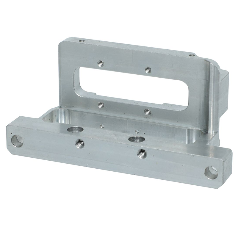
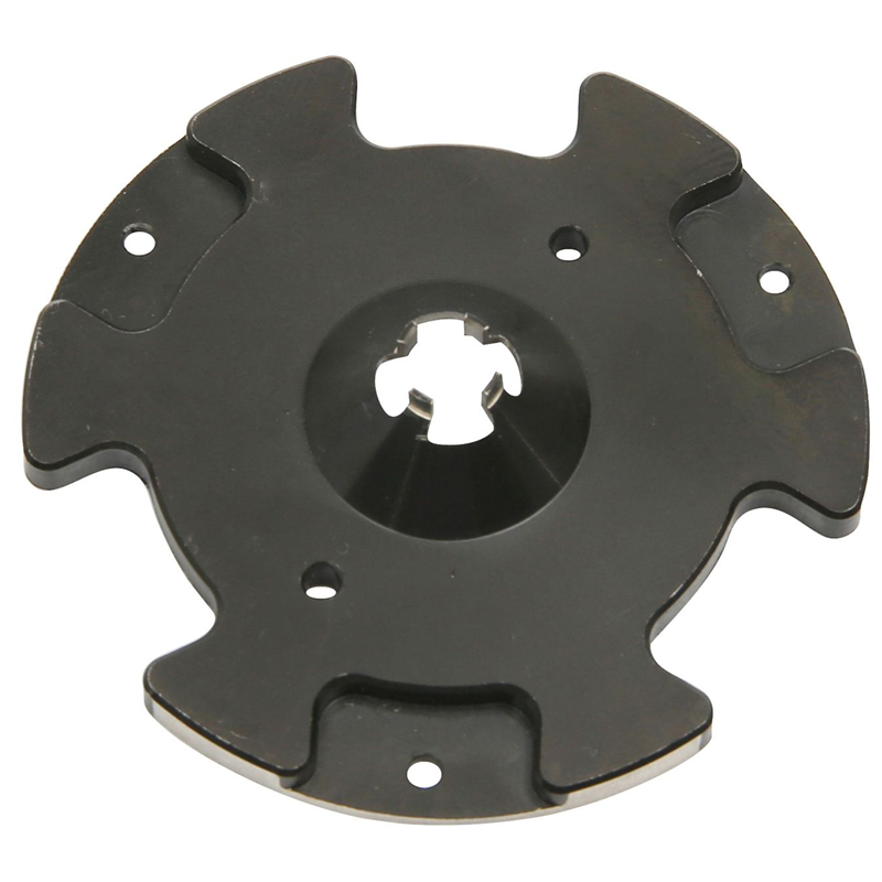
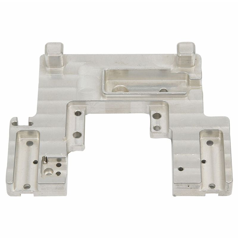
Our custom CNC milling fixture plates are not standard flat mounting plates. They are precision‑machined, multi‑functional foundations engineered for industrial automation, workholding, inspection, and assembly tooling. Manufactured from solid 6061‑T6 aluminum billet, each plate integrates multiple critical features—including locating bosses, precision dowel holes, threaded grids, stepped pockets, clearance cut‑outs, and custom workpiece‑supporting structures—into a single monolithic component.
This integrated approach eliminates the alignment errors and tolerance stack‑up common with assembled modular systems. The result is repeatable positioning accuracy essential for automated production lines, high‑mix manufacturing cells, and quality inspection stations. Whether you require a dedicated jig base, a quick‑change subplate for a CNC machine table, or a custom mounting interface for sensors and actuators, our 3‑axis, 4‑axis, and 5‑axis CNC milling process produces fixture plates that function as the structural datum for your entire tooling system.
Beyond simple mounting, a well‑designed fixture plate can simultaneously provide:
-
Workpiece support and referencing
-
Repeatable locating surfaces via dowel pins or bosses
-
Component mounting interfaces for modular hardware
-
Clearance relief for complex part geometries
-
Clamping access points
-
Sensor or actuator mounting positions
-
Assembly alignment guides
-
Inspection reference surfaces
Key Capabilities at a Glance:
| Feature | Capability |
|---|---|
| Materials | 6061‑T6, 7075‑T6, Stainless Steel (304/316), 45# Steel, and more |
| Tolerances | General ±0.02 mm; Critical locating features ±0.005 mm |
| Flatness | ≤0.02 mm across full plate surface (precision‑ground option available) |
| Surface Finishes | As‑machined, Clear/Black Anodizing, Hard Anodizing, Sandblasting |
| Max Part Size | Up to 1200 mm × 800 mm (larger on request) |
| Lead Times | Prototype: 3‑7 working days; Bulk: 7‑15 working days |
| MOQ | 1 piece (prototype to mass production) |
Beyond fixture plates, our CNC plate manufacturing capability extends to a full range of precision‑machined plate solutions—including mounting plates, base plates, adapter plates, locating plates, and modular subplates. Each plate type is engineered to solve specific structural, locating, or interface challenges across industrial automation, workholding, and assembly tooling systems. Browse our complete CNC plate product lineup to compare standard configurations, or send your drawing for a fully custom design review.
2. Why 6061‑T6 Aluminum? — Material Analysis
6061‑T6 aluminum is our preferred material for automation fixture plates because it offers the optimal balance of machinability, strength, corrosion resistance, weight, and cost‑effectiveness. For most medium‑load industrial jigs and tooling, it delivers reliable, long‑service performance.
Advantages of 6061‑T6 for Fixture Plates
| Property | Value | Benefit for Fixture Plates |
|---|---|---|
| Yield Strength | ~240 MPa | Rigid enough for most workholding and positioning applications |
| Density | 2.70 g/cm³ | Lightweight—reduces load on automation linear modules; easier handling |
| Machinability | Excellent | Clean chip formation for complex pockets, deep reliefs, thin walls, and small threads; reduces tool wear |
| Dimensional Stability | Good | Low thermal deformation; maintains locating stability under normal shop‑floor temperature fluctuations |
| Corrosion Resistance | High | Suitable for shop environments; readily anodizable for added protection and wear resistance |
| Cost Efficiency | High | Lower material and processing cost than 7075 or steel; ideal for most non‑heavy‑load tooling |
When 6061‑T6 May NOT Be the Best Choice
Being transparent about material limitations builds trust. Consider alternatives in these scenarios:
| Application Condition | Recommended Alternative | Reason |
|---|---|---|
| Very high clamping or impact loads | 7075‑T6 Aluminum | Higher strength (~500 MPa yield) with similar machinability |
| Aggressive corrosive or wash‑down environments | Stainless Steel 304/316L | Superior corrosion resistance; no anodizing required |
| Extreme rigidity or high‑wear contact surfaces | Tool Steel / Hardened Steel | Maximum wear resistance and structural stiffness |
| High‑temperature operating conditions | Invar or Tool Steel | Maintains dimensional stability at elevated temperatures |
Our engineering team will recommend the optimal material after reviewing your load, environment, and lifespan requirements—at no cost.
3. CNC Machining Services — Technical Specifications
| Parameter | Specification | Notes |
|---|---|---|
| Product Name | Custom CNC Milling Fixture Plate / Locating Mounting Base Plate | |
| Manufacturing Process | 3‑Axis, 4‑Axis, 5‑Axis CNC Milling, Drilling, Tapping, Boring, Counterboring, Pocketing, Boss Forming | Single‑setup machining maintains datum consistency |
| Available Materials | Aluminum 6061‑T6, 6063, 7075‑T6; Steel 45#, SS304, SS316L; other materials on request | ASTM / EN compliant |
| Max Processing Size | 1200 mm × 800 mm (custom sizes acceptable) | Larger sizes available upon inquiry |
| Plate Thickness Range | 8 – 40 mm (customizable) | Based on rigidity and application requirements |
| Surface Roughness | Ra 0.8 – 3.2 μm (as per drawing) | Precision‑ground finish available for critical datums |
| General Tolerance | ±0.02 mm (for non‑critical features) | Applies to overall dimensions and clearance areas |
| Critical Feature Tolerance | ±0.005 mm to ±0.01 mm | Locating bosses, dowel pin holes, reference datums |
| Hole Positional Accuracy | True position ±0.01 mm | Verified by CMM across full grid pattern |
| Flatness | ≤0.02 mm per 100 mm of plate length | Precision‑ground option: ≤0.01 mm overall |
| Parallelism | ≤0.025 mm (top‑to‑bottom face) | |
| Threads | Metric / Imperial tapping; tolerance 6H | Custom thread sizes available |
| Hole Configurations | Through holes, threaded holes, reamed dowel holes, counterbores, countersinks | Grid patterns: 0.75″ / 20 mm centers (or custom) |
| Surface Treatment | As‑milled, Deburred, Clear/Black Anodizing, Hard Anodizing, Sandblasting, Passivation | Anodizing adds thin layer; dimension compensation available |
| File Formats Accepted | STEP, STP, IGES, X‑T, DWG, DXF, PDF | 2D drawing with tolerances required; 3D model preferred |
| MOQ | 1 piece for prototype; mass‑production available | No minimum for engineering samples |
| Lead Time | Prototype: 3‑7 working days; Bulk: 7‑15 working days | After drawing and DFM approval |
| Quality Control | 100% CMM inspection + ISO 9001:2015 documentation | 3‑year traceable records per serial number |
4. Critical Tolerance & Precision Capability — A Strategic Approach
A common mistake in fixture plate design is applying unnecessarily tight tolerances to every dimension. This drives up machining time and cost without adding functional value.
Our recommended tolerance strategy:
| Feature Type | Recommended Tolerance | Rationale |
|---|---|---|
| Overall outside dimensions | ±0.05 mm | Clearance with machine table or enclosures |
| Non‑critical pockets and clearance areas | ±0.02 mm | Standard machining tolerance; no functional impact |
| General mounting hole positions | ±0.02 mm | Sufficient for standard bolt clearance |
| Locating bosses and dowel pin holes | ±0.005 – 0.01 mm | Directly affects workpiece repeatability |
| Critical reference surfaces (flatness/parallelism) | ≤0.02 mm | Establishes the structural datum |
| Hole‑to‑hole positional relationships | True position ±0.01 mm | Prevents assembly interference across multiple modules |
What we can achieve under optimal conditions:
-
General features: ±0.02 mm (standard)
-
Critical locating features: ±0.005 mm to ±0.01 mm (depending on geometry, feature size, and inspection method)
-
Selected features (best‑case): Approaching ±0.005 mm, subject to part size, material condition, tool access, and CMM verification
Before production, we will work with you to identify which dimensions are truly critical. This ensures our machining and inspection resources are focused where they deliver the greatest functional value—not wasted on over‑specified non‑critical features.
5. Key Manufacturing Challenges & Our Engineering Solutions
Manufacturing a custom fixture plate is significantly more complex than machining a simple flat plate. Here are the core challenges and how we solve them:
Challenge 1: Maintaining Flatness After Material Removal
The Problem: A large amount of material removed by milling releases internal residual stresses from the aluminum blank. This can cause the plate to warp, bow, or twist after machining—destroying flatness on reference surfaces.
Our Solution:
-
Use stress‑relieved aluminum blanks (pre‑stretched / T‑6 condition)
-
Optimized milling sequence: roughing → stress‑relief rest → semi‑finishing → finishing passes
-
Alternating between milling and grinding passes for critical datums
-
Final flatness verified on a granite surface plate with CMM
Result: Flatness ≤0.02 mm across the full plate surface (≤0.01 mm precision‑ground option).
Challenge 2: Positional Accuracy of Distributed Hole Grids
The Problem: A fixture plate may contain dozens or hundreds of threaded holes, dowel holes, and counterbores spread across different zones. Cumulative positioning errors from multiple setups can cause assembly failure when fitting automation modules, sensors, or locating pins.
Our Solution:
-
All critical hole features machined in a single setup on 5‑axis equipment
-
Primary datum features (locating bosses / surfaces) machined first, then used as reference for all subsequent operations
-
100% CMM verification of true position, not just hole‑by‑hole size
-
Position tolerance held to ±0.01 mm across the full grid
Challenge 3: Complex Feature Integration in a Single Part
The Problem: Combining deep pockets, high locating bosses, thin wall sections, U‑shaped relief cut‑outs, and multi‑direction holes in one workpiece can cause vibration, tool deflection, and chatter—resulting in poor surface finish and dimensional errors.
Our Solution:
-
Optimized workholding with custom soft jaws / vacuum fixtures to dampen vibration
-
Progressive toolpath strategies: high‑speed machining (HSM) for roughing; finishing passes with sharp carbide tooling
-
For thin‑wall sections, we use climb milling with reduced radial engagement to minimize cutting forces
Challenge 4: Sharp Internal Corners — Design vs. Reality
The Problem: CAD drawings often call for sharp 90° internal corners inside pockets or stepped recesses. A standard milling cutter has a cylindrical shape with a radius at the bottom—it cannot produce a perfectly sharp internal corner.
Our Solution:
-
We will flag this during our free DFM (Design for Manufacturability) review
-
Options: accept a small fillet radius (recommended), use EDM for sharp corners (added cost), or revise the design
-
We communicate clearly with you before production—no surprises
Challenge 5: Burr Control in Complex Hole Patterns & Cross‑Holes
The Problem: Fixture plates contain numerous tapped holes, counterbores, and intersecting pockets. Hidden burrs inside recessed cavities or at cross‑hole intersections can interfere with locating pins, scratch workpiece surfaces, or prevent proper seating.
Our Solution:
-
Multi‑stage deburring: automated vibratory deburring + manual inspection of critical areas
-
Custom deburring tools for cross‑holes and deep pockets
-
Final edge chamfering and hand‑finish on all accessible features
-
Each plate is inspected for burrs before shipping
6. Application Scenarios
Custom CNC fixture plates are used across a wide range of industries and functions. Below are typical applications and the critical requirements for each:
| Industry / Application | Plate Function | Key Requirement |
|---|---|---|
| CNC Machine Shops | Modular fixture plate / subplate on machine table | Repeatable hole grid; quick‑change capability; reduces setup time |
| Industrial Automation | Mounting base for actuators, sensors, and modules inside a cell | Structural datum; precise hole‑to‑hole relationships |
| Electronics Assembly (3C) | Precision positioning plate for PCBs, housings, and modules | High‑density micro‑locating features; lightweight; black anodizing for anti‑reflective surfaces |
| Semiconductor Equipment | Tooling plate for wafer handling and inspection systems (non‑vacuum) | Ultra‑flat reference surface; tight thermal stability |
| Assembly & Welding Lines | Jig and welding base plate with product‑specific locating bores | Durable clamp zones; repeatable build operations |
| Inspection & Metrology | CMM fixture plate or reference flat | Flatness is the product—known‑flat datum for measurement |
| Vision Inspection Systems | Locating base for cameras, lighting, and test parts | Dimensional stability and non‑reflective surface finish |
| Test & R&D Rigs | Optical breadboards; reconfigurable mounting plates | Flexible hole patterns for iterative testing |
| Medical Device Manufacturing | Custom assembly fixture for production lines | Cleanable surface; anodized finish; corrosion resistance |
| Robotics & Special‑Purpose Machinery | Structural and locating interfaces for end‑effectors, sensors, mechanical modules | Precise mounting interfaces; lightweight for robotic payload |
7. Customization Options — Full Flexibility
We manufacture fixture plates exactly to your requirements. Customization options include:
| Category | Options |
|---|---|
| Dimensions | Any length, width, thickness, or shape to your drawing |
| Hole Grid | Custom pitch, pattern, thread size (metric or imperial); 0.75″ / 20 mm common |
| Hole Types | Through holes, threaded holes, counterbores, countersinks, reamed dowel holes |
| Locating Features | Precision bosses, recessed cavities, stepped surfaces, clearance cut‑outs, locating pins |
| Materials | 6061‑T6 / 7075‑T6 / 6063 / Stainless 304/316 / 45# Steel / Tool Steel |
| Surface Finish | As‑milled / Deburred / Clear Anodizing / Black Anodizing / Hard Anodizing / Sandblasting / Passivation |
| Markings | Engraved hole IDs, part numbers, logos, assembly alignment marks |
| Tolerances | Custom tolerance strategy per your functional requirements |
| Packaging | Protective foam / custom crating for damage‑free shipping |
No minimum order quantity (MOQ). We make one prototype or thousands with equal engineering attention.
8. Quality Assurance & Inspection
Our ISO 9001:2015‑certified facility follows a four‑stage quality gate process:
-
IQC (Incoming Quality Control): Raw material certification verified
-
IPQC (In‑Process Quality Control): Critical features checked during machining
-
FAI (First Article Inspection): Full CMM inspection on first piece
-
OQC (Outgoing Quality Control): Final inspection before packaging
Typical Inspection Methods
| Method | Application |
|---|---|
| Digital calipers / micrometers | General dimensions |
| Height gauges | Step heights, surface parallelism |
| Pin gauges / thread gauges | Hole diameters and thread quality |
| Surface plate & dial indicator | Flatness and parallelism verification |
| CMM (Coordinate Measuring Machine) | True position, hole‑to‑hole relationships, full 3D dimension verification |
| Custom inspection fixtures | For high‑volume repeat orders |
All critical dimensions are verified. Inspection reports are available upon request and retained for 3 years per serial number for full traceability.
9. Frequently Asked Questions (FAQ)
Q1: What exactly is a CNC fixture plate?
A CNC fixture plate is a precision‑machined plate used as a structural, mounting, locating, or supporting element within a jig, fixture, inspection system, or automation cell. Unlike a simple flat plate, it integrates features like locating bosses, dowel holes, threaded grids, pockets, and clearance areas to hold, position, and reference workpieces or components repeatedly.
Q2: What’s the difference between a fixture plate, a subplate, and a mounting plate?
These terms are often used interchangeably but have subtle distinctions:
-
Fixture plate: A grid‑hole plate mounted on a machine table for workholding; often the functional heart of a jig.
-
Subplate: An intermediate plate between the machine table and the fixture; used to adapt different fixturing systems.
-
Mounting plate: Primarily designed to attach one component to another structure.
In practice, one part can perform all three functions—the correct name depends on its primary application.
Q3: What tolerance can you achieve for locating bosses and dowel pin holes?
For critical locating features, we achieve ±0.005 mm to ±0.01 mm, depending on feature size, geometry, material, and inspection method. Tolerances are confirmed during our DFM review before production.
Q4: Can you produce a fixture plate from my drawing only?
Yes. Please send your 2D drawing (with tolerances and surface finish requirements) and 3D CAD model (STEP, STP, IGES, DWG, or PDF). If you only have a physical sample, we also offer reverse‑engineering services.
Q5: Is 6061‑T6 always the best choice for fixture plates?
For most medium‑load automation jigs and tooling, 6061‑T6 is ideal. For heavy clamping loads, consider 7075‑T6 aluminum. For corrosive environments, choose stainless steel 304/316L. Our engineering team will suggest the optimal material after reviewing your application—free of charge.
Q6: Do you offer black anodizing? Will it affect dimensions?
Yes. We provide clear anodizing, black anodizing, and hard anodizing. Anodizing adds a thin oxide layer (typically 0.005–0.015 mm per surface). If dimensions are critical, we compensate by adjusting the machining allowance before anodizing so the final part meets your specifications.
Q7: What is a DFM review? Do you charge for it?
DFM (Design for Manufacturability) is a free pre‑production review where our engineers analyze your design for manufacturability. We flag issues like sharp internal corners, thin‑wall risks, stress‑prone structures, or potential tolerance conflicts—and suggest solutions before we start machining. This saves you time and money.
Q8: Can you integrate quick‑change or zero‑point mounting features?
Yes. We can machine locating bores and hardware patterns compatible with Ball Lock®, zero‑point, or other quick‑change pallet systems. Repeatability of ±0.013 mm is achievable.
Q9: What’s your lead time for a one‑off prototype?
Typically 3‑7 working days for an aluminum fixture plate after drawing and DFM approval. Bulk orders take 7‑15 working days, depending on quantity and complexity.
Q10: Can you manufacture materials other than 6061 aluminum?
Yes. We routinely machine 7075 aluminum, 6063 aluminum, stainless steel (304/316L), 45# steel, tool steel, brass, and selected engineering plastics. Material selection is based on your load, wear, corrosion, weight, and environmental requirements.
Q11: Do you have a minimum order quantity?
No. We accept one‑off prototypes, small batches, and mass‑production orders. Every project receives the same engineering attention.
Q12: What file formats do you accept?
We accept STEP, STP, IGES, X‑T, DWG, DXF, and PDF formats. A 2D drawing with tolerance callouts is required; a 3D model is strongly preferred.
Q13: How do you ensure flatness on large plates?
We use stress‑relieved blanks, optimized roughing‑finishing sequences, and CMM verification. Standard flatness is ≤0.02 mm per 100 mm. For applications requiring tighter flatness (≤0.01 mm overall), we offer a precision‑ground option.
Q14: Do you provide inspection reports?
Yes. Inspection reports (including CMM reports) are available upon request. We retain 3‑year traceable records per serial number.
Q15: How do I get a quote?
Send your 2D drawing, 3D CAD model, material preference, quantity, surface finish, and critical tolerance requirements to our engineering team. We will review manufacturability and provide a detailed quote within 2 business hours of receiving complete files.
10. How to Order
-
Submit your design: Upload your 2D drawing (with tolerances and finish notes) and 3D CAD model (STEP/STP/IGES/DWG/PDF).
-
DFM review: Our engineering team reviews manufacturability and provides feedback—free of charge.
-
Quote & approval: You receive a detailed quote with lead time; confirm to proceed.
-
Production: CNC machining, inspection, surface treatment, and packaging.
-
Delivery: Shipped with inspection documentation (if requested) and full traceability.
Additional information
| material |
|---|

Reviews
There are no reviews yet.