
Table of Contents
ToggleIntroduction
Industries such as aerospace, medical devices, humanoid robotics, UAVs, and advanced automation increasingly demand components with freeform surfaces, deep cavities, and multi-angled features. 5-axis CNC machining has become the essential manufacturing technology for these complex curved parts.
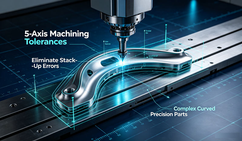
However, achieving precision on these components is far more challenging than traditional 3-axis prismatic machining. While 5-axis machines offer unmatched flexibility, the additional rotary axes introduce more variables—rotary axis accuracy, tool center point (TCP) control, fixture positioning deviations, and geometric tolerance accumulation. For complex curved surfaces, maintaining dimensional accuracy is not just about machine resolution; it requires a complete tolerance management strategy to prevent tolerance stack-up, which can cause assembly mismatches, surface mismatch, sealing failure, and complete product rejection.
This guide systematically analyzes the root causes of cumulative dimensional errors on curved workpieces, explains how single-setup 5-axis machining eliminates stack-up errors at the source, and delivers actionable GD&T tolerance control strategies, process optimization standards, and industry tolerance benchmarks for precision engineers, design drafters, and CNC process technicians.
Part 1: Understanding Tolerances and Stack-Up in 5-Axis Machining
1.1 What Are CNC Machining Tolerances in 5-Axis?
CNC machining tolerance refers to the allowable variation between the designed dimension and the actual manufactured dimension.
- Drawing dimension: Ø20.000 mm
- Tolerance requirement: ±0.005 mm
- Acceptable range: 19.995 – 20.005 mm
In 5-axis CNC machining, tolerance control becomes more complicated because the cutting process involves simultaneous movement along X, Y, Z linear axes and A, B, or C rotary axes. Unlike 3-axis machining, where tool movement mainly depends on linear positioning accuracy, 5-axis machining requires precise coordination between all axes to maintain the correct tool orientation. A small positioning error in a rotary axis can create larger deviations at the cutting point, especially when machining impellers, turbine blades, medical implants, and freeform aerospace structures.
1.2 The “Precision Pyramid”: General vs. Economic vs. Extreme Tolerances
To avoid over-tolerancing, engineers must distinguish between what is theoretically possible and what is economically viable for mass production.
Capability Level | Typical Tolerance Range | Application Scenario | Manufacturing Conditions |
|---|---|---|---|
General/Standard | ±0.01 mm – ±0.03 mm | Standard curved housings, non-critical mating surfaces | Standard 5-axis machines, normal workshop environment |
Precision/High-Grade | ±0.005 mm – ±0.01 mm | UAV frames, robot joint housings, bearing mounts | High-end 5-axis centers, precision fixtures, CMM inspection |
Ultra-Precision/Extreme | ±0.003 mm – ±0.005 mm | Aerospace turbine blades, medical implant sealing surfaces | Temperature-controlled (20℃) workshops, in-process probing, thermal compensation |
Part 2: The Root Causes of Tolerance Stack-Up on Complex Curved Parts
Tolerance stack-up (cumulative dimensional error) refers to the superposition of tiny positioning, clamping, and thermal deformation errors generated at every machining stage along the part’s dimensional chain. For complex continuous curved components, accumulated deviations directly damage profile tolerance, position tolerance of angled holes, smooth surface transition, and assembly matching accuracy.
2.1 Why 3-Axis Multi-Setup Machining Triggers Severe Cumulative Errors
3-axis machining only supports linear X/Y/Z movement without rotary axes. All curved, inclined, and reverse features require separate clamping operations. Three major error sources form the stack-up chain:
1. Datum offset error per re-clamp
Each repositioning redefines the workpiece zero point. Fixture positioning pin clearance, workpiece surface flatness, and clamping force fluctuation create independent positioning deviations for every setup. All geometric features lose a unified global reference frame.
2. Dimensional chain superposition across multiple stations
Angled curved holes, curved mounting bosses, and freeform contours are machined in separate setups. Deviations from each station add up along the spatial dimension chain, breaking the relative position tolerance between curved surfaces and critical mounting holes.
3. Workpiece deformation inconsistency
Different clamping positions change the internal stress distribution of aluminum, stainless steel, and titanium curved blanks. Thin-wall curved components produce variable elastic deformation after each re-clamp, introducing unpredictable shape errors that compound with positioning deviations.
Case Example: For a typical 7075 aluminum UAV full-curved frame, four separate 3-axis setups generate total stack-up errors up to ±0.04 mm, failing the drawing’s profile tolerance requirement of ±0.02 mm.
2.2 The “Butterfly Effect” of Rotary Axes
In 5-axis machining, a seemingly insignificant rotary axis deviation of only 0.01° may create several microns of dimensional error at the tool tip when machining a large component. This occurs because the error radius is amplified by the distance from the rotation center to the cutting point. This is why RTCP (Rotary Tool Center Point) control becomes non-negotiable for complex curved parts.
Part 3: Core Logic — How 5-Axis Single-Setup Machining Erases Stack-Up Errors
5-axis CNC machines add two rotary axes (A/B or C-axis) to linear X/Y/Z axes, enabling arbitrary spatial tool vector orientation. All curved surfaces, inclined holes, deep curved cavities, and contour features can be fully machined within one fixed clamping cycle, fundamentally cutting off the stack-up error chain.
3.1 Unified Global Datum Eliminates Repeated Coordinate Conversion
The workpiece locks to one fixture and maintains a single datum reference frame throughout roughing, semi-finishing, and finishing. All curved contour points, hole positions, and curved bosses share identical zero coordinates, removing datum conversion errors from repeated re-clamping. Relative geometric tolerances between all curved features only depend on the machine’s native linkage precision, not accumulated clamping offsets.
Performance metrics from case studies:
- Achieved coaxiality below 0.008 mm between opposite-direction holes
- Reduced processing time by 38% due to one-time setup
- Lowered scrap rate from 6.2% to 0.9%
3.2 RTCP (Rotary Tool Center Point) and Non-Linear Error Compensation
Advanced 5-axis systems are equipped with RTCP functions to compensate for rotary axis travel deviation. Without RTCP, minor rotation angle errors magnify into large contour deviations at the far end of curved workpieces. RTCP corrects tool tip coordinates in real-time during axis rotation, limiting rotary-induced shape errors within ±0.005 mm for curved surfaces.
Furthermore, for curved surfaces, the interpolation of toolpaths generates chord errors—the deviation between the ideal curved surface and the linear segments used to approximate it. Optimized CAM toolpaths with chord error thresholds below 5 μm are recommended for finishing operations.
3.3 High-Rigidity Fixture Design for Curved Blanks
To fully leverage single-setup machining, fixtures must support thin curved parts with vacuum suction or full-surface contact to avoid cantilever vibration. Align weak blank rigidity directions with minimum cutting force vectors to restrain elastic deformation during curved surface finishing. Additionally, selecting ISO 26623 high-precision tool holders with radial runout ≤0.003 mm is critical, as tool holder eccentricity accounts for nearly 30% of 5-axis curved surface residual errors.
Part 4: Advanced GD&T Rules and DFM Tips for 5-Axis Curved Components
When designing tolerance standards for 5-axis curved parts, engineers must match GD&T symbols to single-setup processing advantages to avoid unnecessary tight tolerances and manufacturing cost inflation.
4.1 Profile Tolerance of Freeform Curved Surfaces (Primary Control)
Single-setup 5-axis stably delivers profile tolerance ±0.015 – ±0.025 mm for aluminum curved parts, and ±0.02 – ±0.03 mm for stainless steel/titanium curved components. Critical rule: Mark global profile tolerance against the primary datum frame instead of local single-surface datums to fully utilize unified coordinate precision.
4.2 Position Tolerance of Angled Curved-Surface Holes
All inclined threaded holes and locating bores on curved surfaces are machined in one setup. Position tolerance can be tightened to ±0.008 – ±0.012 mm without stack-up risk, far superior to 3-axis multi-setup (which is limited to ±0.03 mm minimum).
4.3 Avoid Redundant Composite Geometric Tolerances
Do not add parallelism or flatness secondary tolerances on continuous curved surfaces. Over-specifying tolerances does not improve performance but raises processing difficulty and scrap rate. Separate functional curved surfaces from non-matching decorative curves: only apply tight profile tolerance to assembly mating curved areas; relax tolerance to ±0.04 mm for non-contact outer curved surfaces.
4.4 Apply MMC (Maximum Material Condition) Modifiers
Use MMC modifiers on curved boss locating features to expand tolerance windows while guaranteeing assembly compatibility, significantly reducing over-tolerancing costs.
4.5 Account for Surface Coatings and Thermal Expansion Early
Unmodeled surface coatings (e.g., anodizing) can introduce layers ranging from microns to millimeters. When a standard anodized layer adds 0.001 inches of material to a part with a total tolerance of ±0.0005 inches, the part becomes scrap instantly.
Differentiate between additive and penetrative coatings in simulation software.
For free-form surfaces like turbine blades, allowances should vary—from 0.3 mm in flat areas to 0.8 mm in curved sections—to maintain consistent cutting conditions.
For stainless steel and titanium alloys, expand linear tolerance by 0.005–0.01 mm for large curved parts to compensate for thermal expansion.
Part 5: Industry Tolerance Benchmarks for Typical Curved 5-Axis Parts
Based on mass production data for aerospace, robotics, medical, and UAV curved components, the standard achievable tolerance ranges for single-setup 5-axis machining are summarized below. Important: All data below apply to single-setup 5-axis linkage processing; switching to multi-setup 3-axis will double or triple these tolerance values due to stack-up errors.
Component Category | Material | Curved Surface Profile Tolerance | Angled Hole Position Tolerance | Surface Finish (Ra) |
|---|---|---|---|---|
Humanoid Robot Joint Housing | 7075 Aluminum | ±0.015 mm | ±0.008 mm | 0.8 – 1.0 μm |
UAV Full-Curved Structural Frame | 7075-T6 Aluminum | ±0.020 mm | ±0.010 mm | 1.0 – 1.2 μm |
316 Stainless Steel | ±0.025 mm | ±0.012 mm | 0.6 – 0.8 μm | |
Aerospace Turbine Curved Blade | Titanium Alloy (Ti-6Al-4V) | ±0.010 mm | ±0.006 mm | 0.4 – 0.6 μm |
Compact Gear Reducer Curved Casing | 6061 Aluminum | ±0.020 mm | ±0.010 mm | 1.2 – 1.6 μm |
Part 6: Closed-Loop Inspection Workflow for Tolerance Verification
To fully confirm that stack-up errors are eliminated, implement a two-stage tolerance inspection workflow for curved 5-axis parts.
6.1 In-Process On-Machine Probing
Use machine touch probes to scan workpiece datum points before and after finishing. This process:
- Immediately identifies contour oversize/undersize errors before workpiece removal.
- Avoids scrap from post-machining re-clamp measurement deviations.
- Automatically updates NC code coordinates to compensate for raw blank shape errors.
6.2 Constant-Temperature CMM Full Geometric Inspection
Transfer finished curved parts to a 20℃ temperature-controlled measuring room for coordinate measuring machine (CMM) scanning. Capture full curved surface point cloud data to verify global profile tolerance and inter-feature position tolerance. A comprehensive inspection report should include:
- Dimensional inspection results
- GD&T verification (Profile, Position, Flatness)
- Surface roughness report
- Material certificate (if applicable)
All measurement data should form tolerance traceability records for batch production quality control.
Part 7: DFM Design Tips to Avoid Over-Tolerancing
Many design engineers specify unnecessarily tight tolerances on curved drawings, driving up machining costs without functional gains. Follow these Design for Manufacturing (DFM) rules for balanced precision and cost:
- Define Critical Dimensions Clearly: Avoid applying ultra-tight tolerances to every feature. Specify tight tolerance only where function requires it (e.g., sealing interfaces, bearing fits).
- Unify All Critical Feature Datums: Design all features referencing one primary datum set to maximize the single-setup precision advantage.
- Consider Manufacturing Capability Early: Discuss tolerance requirements with your CNC supplier before production. An early DFM review can reduce manufacturing risks, cost, and lead time.
- Avoid unnecessary ultra-tight tolerances: Avoid ultra-tight ±0.005 mm profile tolerances on large continuous curved surfaces unless required by aerospace-grade sealing standards, as this demands ultra-precision 5-axis equipment and constant-temperature workshops.
FAQ: Common Questions About 5-Axis CNC Tolerances
Q1: What tolerance can 5-axis CNC machining achieve in mass production?
Most precision 5-axis CNC machines can consistently achieve ±0.005 mm under controlled conditions (single setup, proper cooling, rigid fixtures). However, the economic tolerance for standard curved parts is typically ±0.01 – ±0.02 mm to balance quality and cost.
Q2: Why is 5-axis machining significantly better for complex curved parts?
5-axis machining allows continuous tool orientation changes and reduces multiple setups, which eliminates repetitive datum conversion errors. It achieves better surface accuracy, tighter position tolerances on angled holes, and reduces alignment errors by up to 80% compared to multi-setup 3-axis machining.
Q3: Does tighter CNC tolerance always mean better parts?
Not always. Excessively tight tolerances increase machining difficulty, tooling costs, and inspection time. Engineers should define tolerances based on functional requirements (assembly fit, sealing, mechanical performance) rather than arbitrary preferences.
Q4: How do manufacturers inspect 5-axis curved parts?
Common inspection methods include CMM measurement (point cloud scanning), optical scanning, and in-process probing to verify dimensions and geometric tolerances. A combination of in-process probing (for immediate correction) and post-process CMM (for final verification) is the industry best practice.
Q5: What industries require the tightest 5-axis CNC tolerances?
Typical industries include:
- Aerospace & Defense (turbine blades, structural frames)
- Medical Devices (implants, surgical instruments)
- Humanoid Robotics (joint housings, sensor mounts)
- Semiconductor Equipment (precision stages, chambers)
- High-Performance Automotive (prototype components)
Conclusion: Precision 5-Axis Machining Requires Complete Tolerance Chain Management
Tolerance stack-up remains the top precision failure cause for complex curved CNC components. Traditional multi-setup 3-axis machining cannot resolve cumulative positioning and clamping errors, while single-setup 5-axis machining eliminates stack-up errors fundamentally by unifying the workpiece datum reference frame and enabling multi-angle curved feature forming without re-clamping.
By combining RTCP-equipped precision 5-axis equipment, optimized CAM curved toolpaths, standardized GD&T tolerance marking, and closed-loop inspection processes, manufacturers can stabilize curved surface profile tolerance within ±0.010 – ±0.025 mm for mass production.
For design and process engineers, applying this 5-axis tolerance guide reduces rework, improves assembly yield, and balances precision requirements with manufacturing cost. A professional 5-axis CNC machining supplier does not simply manufacture parts—it manages the entire tolerance chain from engineering drawing to final inspection, ensuring that complex curved parts perform flawlessly in their intended applications.


The distinction between general, economic, and extreme tolerances is a useful reminder that tighter specs are not always the best choice for every feature. I also appreciate the focus on stack-up errors in complex 5-axis parts, because datum strategy and inspection planning often have just as much impact on final accuracy as the machining process itself.