
Custom CNC Machined Spur Gear Shaft | Precision Gear Shaft
Description
Custom CNC Machined Spur Gear Shaft
Custom Spur Gear Shaft Manufacturing
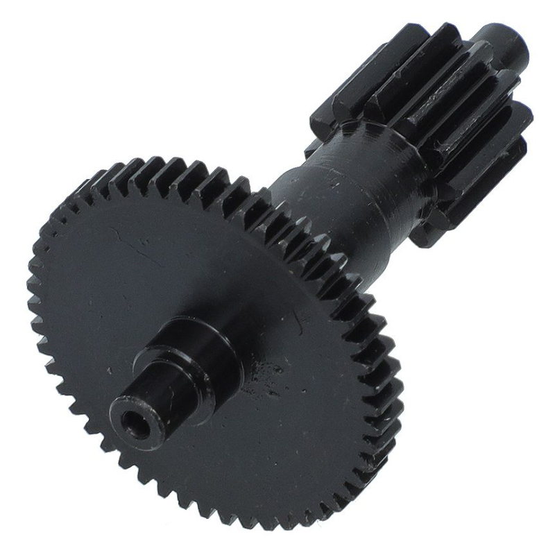
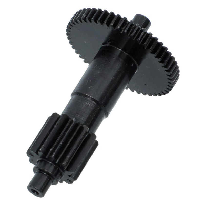
This custom CNC machined spur gear shaft combines a straight-tooth gear and shaft into a single precision mechanical component for power transmission, motion control, and industrial machinery. Unlike a separate gear and shaft assembly, an integrated spur gear shaft is manufactured as one component, helping control gear-to-shaft alignment, concentricity, and overall dimensional accuracy.
XINQIDA provides custom spur gear shaft manufacturing according to customer drawings, 3D CAD models, samples, and technical specifications. Gear module, tooth count, pressure angle, shaft diameter, overall length, keyways, threads, shoulders, grooves, and other features can be customized to meet the requirements of specific transmission systems.
Our CNC machining capabilities support turning, milling, drilling, threading, gear-related machining, keyway machining, surface finishing, and secondary operations. Heat treatment and other external processes can also be coordinated according to material and performance requirements.
Whether you need a prototype, small batch, or production quantity, XINQIDA supplies custom CNC machined gear shafts for industrial automation, robotics, machinery, transmission systems, and other precision mechanical applications.
What Is a Spur Gear Shaft?
A spur gear shaft is a shaft with straight-cut gear teeth integrated into the shaft body. The gear and shaft function as a single rotating transmission component rather than two separately assembled parts.
A custom spur gear shaft may include a single gear section or multiple gear features along the shaft. Depending on the application, additional features such as bearing journals, keyways, splines, threaded ends, retaining grooves, shoulders, flats, and cross holes can be incorporated into the shaft design.
The integrated construction can reduce the number of components in an assembly and provide controlled alignment between the gear teeth and critical shaft features. This is particularly useful in compact transmission systems where concentricity, positioning accuracy, and reliable torque transmission are important.
For applications requiring a pinion function, the same basic configuration can also be manufactured as a pinion shaft when the integrated gear serves as the smaller gear in a transmission pair.
To explore our full range of custom‑manufactured gear components including spur gears, helical gears, bevel gears, gear racks and other transmission parts, please visit our Custom CNC Machining Gear Parts category page.
Spur Gear Shaft Technical Specifications
| Parameter | Custom Manufacturing Capability |
|---|---|
| Part Type | Spur Gear Shaft / Integrated Gear Shaft |
| Gear Type | Spur Gear |
| Material | Carbon Steel, Alloy Steel, Stainless Steel, Aluminum and other specified materials |
| Gear Module | Customized according to drawing |
| Number of Teeth | Customized |
| Pressure Angle | Customized according to drawing |
| Pitch Diameter | Customized |
| Outside Diameter | Customized |
| Shaft Diameter | Customized |
| Overall Shaft Length | Customized |
| Gear Position | Customized along shaft |
| Shaft Features | Shoulders, grooves, journals, flats and other features |
| Keyways | Custom |
| Splines | Custom when required |
| Threads | Metric or inch threads |
| Bore / Holes | Custom according to drawing |
| Dimensional Tolerance | According to drawing and functional requirements |
| Concentricity | Controlled according to application requirements |
| Runout | Controlled according to drawing and functional requirements |
| Surface Finish | According to drawing |
| Heat Treatment | Available according to material and application |
| Surface Treatment | Available according to material and application |
| Manufacturing Processes | CNC Turning, Milling, Drilling, Threading and Gear-Related Machining |
| Production Volume | Prototype, Small Batch and Production Runs |
| Inspection | Dimensional and functional inspection according to requirements |
| Drawing Formats | STEP, STP, IGES, PDF, DWG and other common formats |
Materials for Custom Spur Gear Shafts
Material selection is an important part of spur gear shaft design because the shaft must withstand torque, bending loads, gear tooth forces, wear, fatigue, and the operating environment.
Alloy Steel
Alloy steel is commonly selected for gear shafts used in demanding mechanical transmission applications. Depending on the required performance, suitable alloy steels can provide a combination of strength, toughness, fatigue resistance, and heat-treatment capability.
For applications involving high tooth loads or continuous operation, alloy steel can be considered when higher mechanical strength and wear resistance are required.
Carbon Steel
Carbon steel can be used for gear shafts where the required mechanical strength and wear resistance are within the material’s capability. It can provide a cost-effective solution for selected industrial machinery and transmission applications.
Stainless Steel
Stainless steel can be considered when corrosion resistance is an important design requirement. Depending on the application, stainless steel gear shafts can be used in automation equipment, specialized machinery, and environments where exposure to moisture or corrosive conditions must be considered.
Aluminum
Aluminum can be used for selected lightweight gear shaft applications where reducing rotating mass is important and the transmitted loads are relatively moderate. Material grade, surface treatment, gear loading, and shaft strength should be evaluated together.
Material Selection
The appropriate material depends on:
- Transmitted torque
- Gear tooth load
- Rotational speed
- Shaft diameter
- Required hardness
- Wear resistance
- Fatigue requirements
- Operating temperature
- Corrosion environment
- Heat-treatment requirements
- Production quantity and cost
XINQIDA can manufacture gear shafts according to the material specified on the customer’s drawing or assist with material selection based on the intended application.
CNC Spur Gear Shaft Manufacturing Process
Manufacturing an integrated spur gear shaft requires control of both the shaft geometry and gear geometry. The relationship between the gear teeth, shaft journals, shoulders, keyways, and other critical features can directly affect the performance of the finished transmission component.
1. Material Preparation
The selected material is prepared according to the required dimensions and manufacturing process. Material specifications can be verified according to the customer’s requirements before machining.
2. CNC Turning
CNC turning establishes the main shaft geometry, including shaft diameters, bearing journals, shoulders, grooves, and other rotational features.
Critical shaft dimensions are machined according to the drawing to establish the required fit with bearings, couplings, housings, or other mating components.
3. Gear Machining
The gear section is produced according to the specified gear geometry, including module, tooth count, pressure angle, pitch diameter, tooth thickness, and other design requirements.
The appropriate gear manufacturing method depends on the gear geometry, material, required accuracy, production quantity, and final application.
4. Keyway, Thread and Secondary Machining
Additional features can be machined after or during the primary machining operations.
Typical secondary features include:
- Keyways
- Splines
- Threaded ends
- Retaining grooves
- Cross holes
- Flats
- Shoulders
- Bearing journals
- Mounting features
5. Heat Treatment
Heat treatment can be specified when increased hardness, wear resistance, fatigue strength, or service life is required.
Depending on the material and application, possible treatments may include carburizing, quenching, tempering, induction hardening, or other specified processes.
Heat-treatment requirements should be defined before production because they can affect dimensional stability and the final machining sequence.
6. Grinding and Finishing
When tighter dimensional requirements or improved surface finish are required, selected shaft journals or gear surfaces may require grinding or additional finishing operations.
The final process is determined according to the drawing, gear accuracy requirements, material, heat-treatment condition, and functional requirements.
7. Inspection
Finished gear shafts are inspected according to the critical requirements specified by the customer.
Inspection may include:
- Shaft diameter inspection
- Overall length inspection
- Gear dimensions
- Tooth-related dimensions
- Concentricity
- Runout
- Keyway dimensions
- Thread dimensions
- Surface finish
- Hardness after heat treatment
- Final dimensional inspection
Inspection documentation can be provided when required for the project.
Spur Gear Shaft Design Considerations
Good gear shaft design should consider both the gear geometry and the mechanical requirements of the shaft.
Gear Module and Tooth Count
Module and tooth count determine important gear dimensions and influence the transmission ratio, gear diameter, and tooth loading.
These parameters should be selected based on the required torque, rotational speed, mating gear, available installation space, and expected operating conditions.
Shaft Diameter
The shaft diameter must provide sufficient torsional and bending strength while remaining compatible with bearings, couplings, seals, and other mating components.
The shaft should not be unnecessarily oversized, because excessive material can increase weight, machining time, and cost.
Gear-to-Shaft Concentricity
For an integrated gear shaft, the relationship between the gear teeth and critical shaft journals is especially important.
Poor alignment or excessive runout can affect transmission smoothness, tooth contact, vibration, noise, and service life.
Critical concentricity and runout requirements should therefore be specified on the engineering drawing where necessary.
Keyways and Splines
Keyways and splines may be required to connect the shaft to another rotating component.
The selected connection should be based on transmitted torque, assembly requirements, available space, and the design of the mating component.
Gear Position
The position of the gear along the shaft can affect bearing arrangement, load distribution, housing design, and assembly.
When possible, the gear location should be defined relative to important datum features.
Heat Treatment
For higher-load applications, heat treatment may be required to improve tooth hardness, wear resistance, and fatigue performance.
The material, hardness requirement, heat-treatment process, and final machining sequence should be considered together.
Manufacturing Tolerances
Not every feature requires an extremely tight tolerance.
Functional dimensions such as bearing journals, gear-to-shaft alignment, critical mounting surfaces, and mating features should receive appropriate tolerances based on their actual function.
This approach can improve manufacturability while avoiding unnecessary machining costs.
Precision and Tolerance Control for Gear Shafts
Precision gear shaft manufacturing requires control of multiple dimensional relationships rather than simply achieving the nominal shaft diameter.
Important characteristics may include:
- Shaft diameter tolerance
- Bearing journal tolerance
- Gear-to-shaft concentricity
- Radial runout
- Gear tooth dimensions
- Keyway position
- Thread accuracy
- Shoulder location
- Overall length
- Surface finish
- Heat-treatment hardness
For precision transmission components, the gear and shaft should be evaluated as an integrated system.
For example, a shaft may have an acceptable shaft diameter but still perform poorly if the gear section has excessive runout relative to the bearing journals.
XINQIDA therefore recommends defining critical tolerances according to the actual function of the gear shaft rather than applying the same tight tolerance to every feature.
Final achievable tolerances depend on material, geometry, shaft length, gear size, machining process, heat treatment, and inspection requirements.
Spur Gear Shaft vs. Separate Gear and Shaft
| Feature | Integrated Spur Gear Shaft | Separate Gear + Shaft |
| Construction | Gear and shaft are manufactured as one component | Gear and shaft are separate components |
| Assembly | No separate gear-to-shaft assembly required | Requires assembly between gear and shaft |
| Component Count | Lower | Higher |
| Alignment | Gear-to-shaft relationship is controlled during manufacturing | Depends on the assembly interface |
| Concentricity | Can be controlled as one machined component | Influenced by gear bore, shaft fit, and assembly |
| Packaging | Compact integrated structure | May require additional assembly space |
| Maintenance | Replacement may require replacing the integrated part | Individual gear or shaft can potentially be replaced |
| Customization | Gear and shaft geometry can be designed together | Gear and shaft are designed as separate components |
| Best Application | Compact custom transmission components | Modular systems requiring replaceable components |
An integrated spur gear shaft can be advantageous when a compact structure and controlled gear-to-shaft relationship are important.
However, a separate gear and shaft may be preferable when maintenance, component replacement, or modular assembly is a priority.
The best design depends on the mechanical system and production requirements.
Spur Gear Shaft Applications
Custom spur gear shafts are used in mechanical transmission systems where a gear and shaft need to operate as an integrated rotating component.
Typical applications include:
Industrial Automation
Spur gear shafts can be used in automated machinery, positioning mechanisms, motion-control systems, and custom transmission assemblies.
Robotics
Compact integrated gear shafts can be used in robotic transmission mechanisms where space, rotational accuracy, and reliable torque transmission are important.
Gearboxes and Reducers
Gear shafts can function as input shafts, output shafts, intermediate shafts, or transmission shafts within customized gearbox assemblies.
CNC Machinery
Precision gear shafts may be used in machine tools and mechanical drive systems where controlled rotation and accurate mechanical transmission are required.
Packaging Machinery
Gear shafts can be used in rollers, drive mechanisms, indexing systems, and other mechanical transmission components.
Material Handling Equipment
Custom gear shafts can be designed for conveyors, actuators, drive mechanisms, and other industrial equipment.
Automotive and Transportation Equipment
Depending on the design and performance requirements, gear shafts can be used in selected transmission and mechanical drive components.
For deeper engineering guidance on drivetrain performance, NVH optimisation and fatigue‑oriented layout, read our article: Structural Design of Precision Automotive Gear Shaft.
Custom OEM Machinery
Build-to-print gear shafts can be manufactured for specialized machinery and OEM mechanical assemblies where standard components do not meet the required dimensions or performance.
Custom Gear Shaft Manufacturing for OEM Applications
XINQIDA manufactures custom gear shafts according to customer drawings and technical specifications rather than limiting customers to standard catalog dimensions.
You can specify:
- Gear type
- Gear module
- Tooth count
- Pressure angle
- Gear diameter
- Shaft diameter
- Shaft length
- Gear position
- Keyways
- Splines
- Threads
- Bearing journals
- Surface finish
- Heat treatment
- Dimensional tolerances
- Quantity
For new projects, customers can provide a 2D engineering drawing, 3D CAD model, sample, or available technical specifications.
Our engineers can review the part structure and machining requirements before production to identify potential manufacturing issues and clarify critical dimensions.
Why Choose XINQIDA for Custom Spur Gear Shafts?
Custom Manufacturing
We manufacture gear shafts according to customer drawings, samples, and specifications instead of limiting production to standard off-the-shelf designs.
CNC Machining Capability
CNC turning, milling, drilling, threading, and secondary machining can be combined according to the geometry of the gear shaft.
Prototype to Production
Custom gear shaft projects can be developed from prototypes and small batches through subsequent production requirements.
Material and Process Support
Material selection, machining sequence, heat treatment, surface treatment, and finishing requirements can be coordinated according to the application.
Dimensional Inspection
Critical dimensions can be inspected according to the engineering drawing and project requirements before shipment.
Build-to-Print OEM Parts
Customers can submit drawings or CAD models for custom manufacturing of non-standard gear shafts for machinery and equipment.
What Information Is Needed for a Gear Shaft Quotation?
For an accurate quotation, please provide as much of the following information as possible:
- 2D engineering drawing or 3D CAD model
- Gear type
- Gear module
- Number of teeth
- Pressure angle
- Gear diameter
- Shaft diameter
- Overall shaft length
- Material
- Heat-treatment requirements
- Surface-treatment requirements
- Critical tolerances
- Concentricity or runout requirements
- Required quantity
- Expected production schedule
A complete drawing is preferred because it allows the machining process, material, tolerance, inspection requirements, and production cost to be evaluated more accurately.
Custom Spur Gear Shaft FAQ
What is a spur gear shaft?
A spur gear shaft is a shaft with straight-cut gear teeth integrated into the shaft body. It combines the functions of a rotating shaft and spur gear into one mechanical transmission component.
Can you manufacture custom spur gear shafts?
Yes. XINQIDA manufactures custom spur gear shafts according to customer drawings, CAD files, samples, and technical specifications.
Can the gear and shaft be manufactured as one piece?
Yes. An integrated spur gear shaft can be manufactured as one component when the design and manufacturing process are suitable for the required gear and shaft geometry.
What materials can be used for spur gear shafts?
Common material options include carbon steel, alloy steel, stainless steel, and aluminum. The final material should be selected according to torque, gear load, wear, fatigue, corrosion, weight, and heat-treatment requirements.
Can spur gear shafts be heat treated?
Yes. Heat treatment can be specified according to the material and application. Options may include carburizing, quenching, tempering, induction hardening, or other specified treatments.
Can you manufacture precision gear shafts?
Yes. Precision gear shafts can be manufactured according to specified dimensional, concentricity, runout, surface finish, and gear-related requirements. Final achievable accuracy depends on part geometry, material, machining process, heat treatment, and inspection requirements.
What is the difference between a spur gear shaft and a pinion shaft?
A spur gear shaft describes a shaft with straight-cut gear teeth integrated into the shaft. A pinion shaft refers specifically to a shaft carrying a pinion, which is generally the smaller gear in a gear pair. A spur gear shaft can therefore also be a pinion shaft when its gear functions as the pinion.
What is the difference between a gear shaft and a gear drive shaft?
A gear shaft describes the physical component—a shaft with an integrated or mounted gear. A gear drive shaft generally emphasizes the shaft’s function within a drive or transmission system. Depending on the design, the same component can be described using both terms.
Can you manufacture gearbox input and output gear shafts?
Yes. Custom gear shafts can be designed as input shafts, output shafts, intermediate shafts, or other transmission components when the required gear and shaft specifications are provided.
Can you manufacture gear shafts from samples?
Yes. A physical sample can be used as a reference for custom manufacturing. A drawing or CAD model is preferred when available because it provides clearer information about critical dimensions and tolerances.
Can you produce prototype and small-batch gear shafts?
Yes. Custom CNC machining can support prototype, small-batch, and production quantities according to the part geometry and manufacturing requirements.
Explore More Custom Shaft Solutions
Beyond integrated spur gear shafts, we produce a wide variety of custom precision shafts for power transmission, positioning and assembly. Browse our full lineup via the CNC‑Machined Shaft Parts category page to discover spline shafts, stepped shafts, drive shafts and other custom‑machined shaft components.
Get a Quote for Your Custom Spur Gear Shaft
Need a custom spur gear shaft manufactured to your drawing?
Send XINQIDA your 2D drawing, 3D CAD model, sample, material specification, required quantity, and critical tolerance requirements.
Our engineering team can review the design, recommend a suitable machining process, and provide a quotation for your custom CNC machined gear shaft.
Request a Custom Gear Shaft Quote →
Send Your Drawing →
Get Custom CNC Machining Support →
Additional information
| material |
|---|
Reviews
There are no reviews yet.