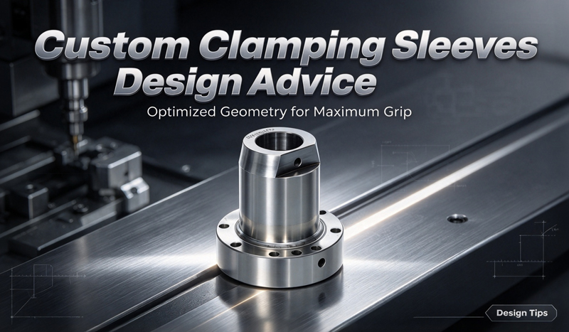
Low-volume custom clamping sleeves are rarely off-the-shelf components. Widely adopted in industrial automation, robotics and specialized machinery, they are commonly requested for prototype validation, equipment retrofits and small-batch replacement parts.
For European and US technical buyers, the core challenge is not just finding a workshop capable of machining clamping sleeves. The real task is to build a design & manufacturing strategy that controls costs, maintains only necessary precision, and delivers reliable clamping performance, without overpaying for unnecessary tight tolerances or complex geometry.
This practical design guide shares actionable advice for engineers and procurement teams before releasing drawings or submitting RFQs, helping reduce manufacturing risks, shorten lead times, and eliminate avoidable cost drivers for custom clamping sleeves, including split clamping sleeves, taper clamping sleeves and hydraulic clamping sleeves.
Table of Contents
Toggle1. Start from Functional Requirements, Not Default Tight Tolerances
The single largest source of inflated cost for custom clamping sleeves is over-specification of tolerances. Tight tolerances are achievable on CNC machines, but every tolerance requirement must be justified by actual function.
Before finalizing your drawing, define clearly what your clamping sleeve needs to accomplish:
- Will it transmit torque, prevent axial sliding, or only serve as a positioning locator?
- Does it need repeated disassembly and re-clamping, or one-time assembly?
- What loads, vibration, temperature and corrosive media will it endure?
- Which features dominate the fit and clamping behaviour: inner bore, concentricity, split slot geometry or axial locating faces?
For most low-volume clamping sleeves, only one or two features are critical to performance, typically the mating bore and slot structure. Applying tight GD&T across every dimension raises machining cycles, inspection workload and scrap risk with zero performance gain. The recommended workflow: apply strict geometric tolerances only on functional surfaces, and use ISO 2768 general tolerances for all non-critical features.
| Feature | Design consideration | Recommended approach |
|---|---|---|
| Internal bore | Shaft fit, clamping uniformity and slip resistance | Specify tolerance based on mating shaft and required interference |
| Outer diameter | Housing clearance / outer mounting | Use clearance fit unless outer surface acts as locating surface |
| Shoulder face | Axial positioning | Control flatness / perpendicularity only if required for location |
| Split slot | Elastic deformation & clamping range | Define slot width, length and internal radii |
| Screw holes | Fastener load transfer and assembly access | Tight position tolerance only when alignment is critical |
| Non-functional edges | Deburr and handling | Avoid strict precision requirements |
2. Material Selection: Match Grade to Operating Conditions & Machinability
Material choice directly impacts strength, wear resistance, corrosion performance, machining time and final cost. For low-volume orders, the most expensive or highest-strength material is not always the best option. Prioritize standard, readily available grades to keep lead times and pricing predictable.
Common CNC machining material options for clamping sleeves:
- 6061-T6 Aluminum: Lightweight, excellent machinability, low cost. Best for light-load split clamping sleeves. Surface anodizing can be added for wear and corrosion protection.
- 1045 / 4140 Alloy Steel: Ideal for high torque, heavy-duty locking sleeves. Heat treatment improves hardness and wear resistance, but you must account for potential thermal distortion.
- 304 / 316L Stainless Steel: For corrosive environments, exhaust clamping sleeves and sensor assemblies such as ABS sensor clamping sleeves. Longer machining cycles and higher raw material cost should be expected.
- Brass / Bronze: Low-friction material for precision, light-load clamping applications.
Specialty materials can be used when corrosion, extreme temperature or heavy wear is required, but be aware they often come with higher minimum order costs, longer lead time and more complex machining. When dissimilar metals are assembled together, evaluate galvanic corrosion risks at the design stage. If coating or plating is required, calculate coating thickness and reserve dimensional allowance for critical mating bores.
3. Optimize Geometry for Low-Volume CNC Machining
Low-volume manufacturing has a unique cost structure: programming, workpiece fixturing, setup and first-article inspection make up a large share of total pricing. Every extra clamping operation or custom cutting tool adds significant cost.
Most clamping sleeves are rotationally symmetric, so design for turning first to maximize efficiency:
- Keep axisymmetric geometry where possible. Features like OD, bore, chamfers and grooves can be completed in a single turning setup to reduce alignment error and re-fixturing cost.
- Avoid deep small-diameter bores and hard-to-reach undercuts unless functionally mandatory.
- Use standard tool radii, drill sizes and fastener thread specifications to avoid custom cutting tools.
- Maintain reasonable wall thickness. Extremely thin walls will deflect during turning, milling or slotting, causing dimensional instability and higher scrap rates. Use gentle wall transitions to improve rigidity without sacrificing elastic deformation for clamping.
For split clamping sleeves requiring slits:
- Add internal radii at slot endpoints to eliminate sharp-corner stress concentration.
- Avoid overly narrow slots. Wire EDM can deliver precise slot width for low-volume prototypes, but it is slower than milling.
- Symmetrically arrange multiple slots to minimize uneven deformation under clamping force.
For hydraulic clamping sleeves, simplify oil grooves and sealing grooves as much as possible. Narrow, intricate groove geometry greatly increases machining time and inspection complexity.
4. Specify Surface Finish Based on Actual Functional Needs
Surface finish affects friction, wear and corrosion resistance, but blanket ultra-fine Ra requirements for all surfaces are a common waste of budget.
Define surface finish selectively:
- Internal bore & clamping contact surfaces: Specify Ra 0.8 μm ~ Ra1.6 μm for high-precision fit and low wear.
- Axial locating faces: Control flatness and surface roughness if axial positioning accuracy matters.
- Non-functional outer surfaces: Standard machined finish is sufficient, unless cosmetic or environmental requirements apply.
Surface treatment plans must be coordinated with dimensional requirements. Anodizing, passivation or plating will add material thickness. You need to pre-compensate the bore dimension before coating, otherwise the final shaft fit will be out of tolerance.
5. Apply GD&T Wisely, Do Not Over-Constrain the Part
GD&T is extremely useful for clamping sleeves to define concentricity, cylindricity, perpendicularity and positional requirements. However, overcomplicated GD&T schemes increase inspection difficulty and cost for small batches.
Follow these rules:
- Build a datum scheme based on the actual machining and inspection workflow.
- Apply concentricity or cylindricity tolerance only to surfaces controlling shaft alignment.
- Avoid tight position tolerances on holes or features that do not impact clamping performance.
- Discuss inspection methods with your supplier early: decide whether CMM measurement, bore gauges or functional gauges are suitable for your tolerance level.
Invite your CNC manufacturer into DFM review before drawings are finalized. Experienced suppliers can propose optimized datum structures to cut inspection costs while preserving your required clamping performance.
6. Inspection, Acceptance Criteria & Quality Planning
Inspection is an essential step for custom low-volume clamping sleeves, especially for replacement parts that must mate with existing equipment. Agree on acceptance criteria before production starts, not after parts are manufactured.
A typical acceptance package may contain:
- First Article Inspection (FAI) report with measured critical dimensions
- Material test certificate
- Heat treatment certificate, if applicable
- Surface roughness measurement on defined critical surfaces
- Fit / clamping functional test, where required
100% full dimensional inspection is rarely economical for low-volume runs. A practical strategy: complete full first-article inspection, plus targeted in-process checks on key features for the rest of batch.
7. RFQ Guide: What to Send to Your CNC Supplier
A complete RFQ package helps manufacturers assess risks and provide accurate, stable quotations. Include below items whenever available:
| Information | Value |
|---|---|
| 2D dimensioned engineering drawing | Defines dimensions, GD&T, threads and tolerances |
| 3D CAD file | Evaluate geometry, tool access and machining strategy |
| Material grade, heat treatment & surface finish | Material planning and dimensional allowance calculation |
| Order quantity | Allocate setup cost and production scheduling |
| Working conditions & assembly method | Help supplier verify material and design suitability |
| Required inspection documents | Clarify quality reporting obligations |
If your design is still in progress, request an early DFM review. Minor adjustments suggested at this phase can reduce total component cost by 20–35%, while fully preserving clamping function.
8. Prototype Validation & Scalability
Low-volume orders often serve product testing, pilot runs or legacy equipment spare parts. It is wise to build a simple validation workflow:
- Confirm drawing: double-check dimensions, tolerances, material and critical interfaces
- Complete DFM review with your machining partner
- Produce the first batch
- Inspect all critical features
- Perform assembly and clamping functional testing
- Update design for future orders if issues are identified
For small quantities, conventional CNC turning & milling is usually more cost-effective than custom dedicated tooling. If future demand may grow, evaluate design scalability at the initial design stage.
9. Pre-RFQ Design Checklist
Before sending your clamping sleeve drawing for quotation, go through this checklist:
✅ Is bore tolerance defined according to shaft fit and clamping function?
✅ Is concentricity only specified for alignment-critical surfaces?
✅ Are wall thickness and slot geometry resistant to machining distortion?
✅ Can most features be completed in a single turning setup?
✅ Surface finish requirements are only applied to functional surfaces
✅ Selected material is standard and available in small batch sizes
✅ Heat treatment and coating effects on critical dimensions are considered
✅ DFM review completed by your machining supplier
✅ First article inspection criteria agreed
✅ Quotation requested for both prototype and low-volume batch quantity
FAQ: Frequently Asked Questions for Low-Volume Custom Clamping Sleeves
What is a clamping sleeve used for? A clamping sleeve grips, locates or connects cylindrical shafts, transmitting torque or preventing axial movement. Split, taper and hydraulic clamping sleeves are widely used for different locking and positioning requirements.
Can clamping sleeves be made in small quantities? Yes. CNC turn-mill machining is suitable for prototype and low batch custom sleeves. The optimal manufacturing process depends on geometry, material, tolerance and order size.
How to reduce the cost of low-volume custom clamping sleeves? Focus tolerances only on functional features, simplify non-essential geometry, use standard materials and fasteners, minimize machining setups, and provide complete drawings for DFM review.
What tolerances can CNC machining achieve for clamping sleeves? Achievable tolerance depends on material, part size, geometry, fixturing and inspection method. Do not apply universal tight tolerance to all features. Confirm feasible tolerance limits with your supplier before production.
CNC turning or milling for clamping sleeves? CNC turning is most efficient for rotational cylindrical bodies. Milling, wire EDM or laser cutting are used for slots, flats and cross holes. Turn-mill combined machines handle complex parts in fewer setups.
Conclusion
Low-volume custom clamping sleeves do not need to be expensive or difficult to manufacture. The core principle is designing for function first, selecting standard materials and proven machining processes, and only specifying tight tolerances where they directly affect clamping performance.
By collaborating with your CNC manufacturer at the early design phase, you can identify potential manufacturability issues before they become costly production defects.
For OEMs and engineering teams sourcing custom clamping sleeves: always ask one question before locking your drawing: Which features directly control clamping performance, and which tolerances are just added out of habit?
The answer will nearly always reveal opportunities to cut cost, shorten lead time, while maintaining the required reliability.
Need custom clamping sleeves manufactured to your specification? Send your 2D drawings or 3D CAD files to XINQIDA. Our engineering team will review material options, tolerance feasibility and manufacturability, and prepare a quotation for your required batch quantity.