
Custom CNC Machined Aluminum Servo Motor Mounting Base
Description
1. Product Overview (The Engineered Solution)
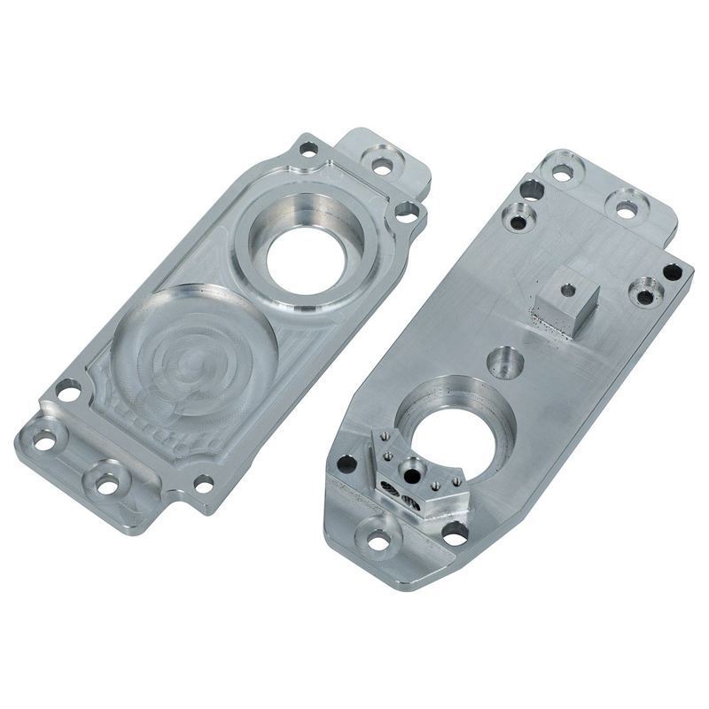
This is a single-piece, dual-sided precision CNC machined aluminum component, serving as the structural backbone for servo motors and robotic actuators.
-
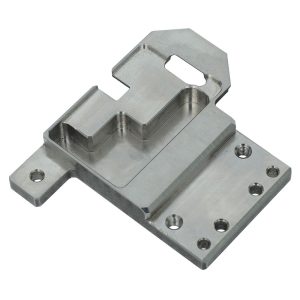
The Front Face (Left Image): Features a deep-milled precision cavity and a concentric through-hole. This cavity is engineered to house the motor stator, rotor, or electromagnetic shielding.
-
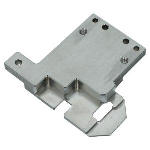
The Rear Face (Right Image): Features a complex, multi-tiered stepped mounting surface, a raised square boss (for electrical connectors/terminals), and precisely positioned dowel holes. This side is designed to mount the entire motor assembly onto a robotic arm, automated platform, or industrial machine.
Unlike simple flat plates or two-part housings, this is a monolithic structural part that integrates cavity containment with multi-functional precision mounting, requiring advanced dual-side machining techniques.
2. Our custom aluminum CNC machining service Parameter Table (Standard Capabilities)
| Parameter Category | Specification & Capabilities |
|---|---|
| Processing Equipment | 4-Axis & 5-Axis CNC Milling Centers (Vertical) with dual-side clamping capability. |
| Raw Material Options | 6061-T6, 7075-T6, 6063 Aluminum Alloys (or custom alloys). |
| Tolerance Standard | ISO 2768-mK / Custom: ±0.01mm (0.0004″) for concentric through-holes and critical mounting bosses. |
| Surface Roughness (Ra) | Front Cavity: Ra 1.6 ~ 3.2 μm / Rear Mounting Face: Ra 0.8 ~ 1.6 μm. |
| Surface Treatment | Clear/Black Anodize, Hard Anodize, Sandblasting + Anodizing, Passivation. |
| Inspection Equipment | CMM (Coordinate Measuring Machine), Optical Comparator, Height Gauge, Pin Gauges. |
| Quality Assurance | ISO 9001:2015 certified. Full First Article Inspection (FAI) and dimensional reports provided. |
| MOQ (Minimum Order) | 1 piece (Prototype) to mass production (flexible MOQ). |
| Lead Time | 5-7 working days for samples; 15-20 working days for mass production. |
3. Application Scenarios (Where It Is Used)
Because this single part serves as both a motor enclosure and a high-precision structural mount, it is widely used in:
-
Industrial & Collaborative Robots (Cobots): Acts as the robot joint housing, where the front cavity contains the joint’s servo motor, and the rear face rigidly connects to the mechanical arm structure.
-
Semiconductor & Wafer Handling Equipment: Used in cleanroom robotic arms and precision alignment stages. The deep front cavity helps isolate moving parts to prevent particle shedding, while the rear face guarantees ultra-precise installation.
-
Precision Automated Inspection & Vision Systems: Serves as the central mounting block for rotary stages, where the through-hole allows for cabling or optical paths to pass through the center.
-
High-End UAV (Drone) Gimbal & Actuator Systems: Lightweight aluminum construction combined with high rigidity makes it ideal for flight control servo mechanisms.
4. Material Analysis: Why 6061-T6 Aluminum?
We strongly recommend Aluminum 6061-T6 for this dual-sided component due to its unique properties:
-
High Strength-to-Weight Ratio: Provides the necessary structural rigidity to resist twisting forces during high-torque motor operation, while keeping the total weight low (critical for robotics).
-
Excellent Machinability for Deep Cavities: Aluminum’s low cutting force allows us to mill the deep front cavity without causing significant tool deflection, maintaining the precise concentricity between the cavity and the central bore.
-
Stress Relieved for Dimensional Stability: As this is a single piece with significant material removed on both sides, 6061-T6 (when properly stress-relieved before machining) guarantees that the part won’t warp or twist when the clamps are released.
-
Corrosion Resistance: After Type II or Type III hard anodizing, it creates an abrasion-resistant, non-conductive surface ideal for harsh industrial environments.
5. Tolerance Capabilities (Engineering Precision)
For this specific dual-sided design, we achieve rigorous geometric tolerances:
-
Coaxiality (Concentricity): 0.015mm TIR. The central through-hole (for the motor shaft) must be perfectly coaxial with the outer diameter of the front cavity. We achieve this by machining both features in the same clamping setup.
-
Parallelism between Front and Rear Faces: 0.025mm over the total length. This ensures that when the motor is installed in the front cavity, the rear mounting face sits perfectly flush against the machine frame without introducing tilt.
-
Hole-to-Hole Positional Accuracy: ±0.02mm (0.0008″) across all mounting holes and dowel holes. Essential for ensuring the alignment of the servo motor with the subsequent mechanical transmission (e.g., harmonic drive).
-
Geometric Flatness: 0.025mm for the rear mounting interface, ensuring vibration-free operation and consistent contact pressure.
6. Manufacturing Challenges (How We Overcome Them)
Machining a single high-precision part from both sides presents distinct technical hurdles that we expertly manage:
-
Challenge 1: Double-Side Fixturing & Alignment
-
Solution: After machining the front cavity, we use precision soft jaws or custom vacuum fixtures that locate off the newly machined features (without scratching them) to machine the rear face. We use Zero-Point Clamping Systems to guarantee that the X/Y zero coordinates remain identical on both sides.
-
-
Challenge 2: Eliminating Machining Distortion (Stress Relief)
-
Solution: Removing massive amounts of material (like the front deep cavity) unbalances the internal stress of the aluminum block. We perform a rough-milling cycle on both sides, leave 0.2mm of stock, and then send the part through a stress-relieving thermal treatment (or wait 24-48 hours for natural stress release) before finishing the final critical dimensions to prevent warping.
-
-
Challenge 3: Thin-Wall Vibration Control
-
Solution: The deep cavity creates thin walls around the perimeter. We utilize High-Speed Machining (HSM) with adaptive clearing toolpaths. This reduces radial cutting forces, preventing the thin walls from “chattering” and ensuring a smooth, dimensionally accurate surface finish.
-
-
Challenge 4: Strict Deburring of Intersecting Holes
-
Solution: The rear face has complex stepped areas with numerous intersecting small threaded holes (for sensors). We use a combination of custom micro-deburring brushes and ultrasonic cleaning to ensure no microscopic metal shavings remain, which could damage the internal motor encoder.
-
7. Frequently Asked Questions (FAQ)
Q1: How do you ensure the front cavity and the rear mounting holes are perfectly aligned?
A: We utilize a single datum reference strategy. Our CNC programmers align all critical features (the central through-hole, the front cavity O.D., and the rear dowel holes) to the same X/Y coordinate system using our 4-axis/5-axis machines and precision fixtures.
Q2: Will the part warp after the deep front cavity is milled?
A: Standard aluminum bars have internal stress. To prevent warping, we use a “Roughing + Stress Relief + Finishing” process. We rough machine both sides to remove 90% of the material, stress-relieve the part, and then perform the final high-precision finishing passes. This guarantees flatness and straightness.
Q3: Can you do surface treatments on both sides differently?
A: Yes. If you require the front cavity (to remain untouched or rough) and the rear face (to be sandblasted and anodized), we use selective masking (with precision silicone plugs and tapes) before anodizing to achieve different surface finishes on the two faces.
Q4: Do you support engineering design changes for this part?
A: Absolutely. We offer DFM (Design for Manufacturing) feedback. If the central cavity depth or the size of the rear mounting boss needs adjustments to fit your specific motor, we can easily modify the CNC program at the prototyping stage.
Q5: What file format do you need for this dual-sided part?
A: We recommend sending 3D STEP (.stp) or Parasolid (.x_t) files. For dual-sided machining, a 3D model is essential so our programmers can correctly simulate the machining of both the front and the back face in the software before actual cutting begins.
Additional information
| material |
|---|

Reviews
There are no reviews yet.