

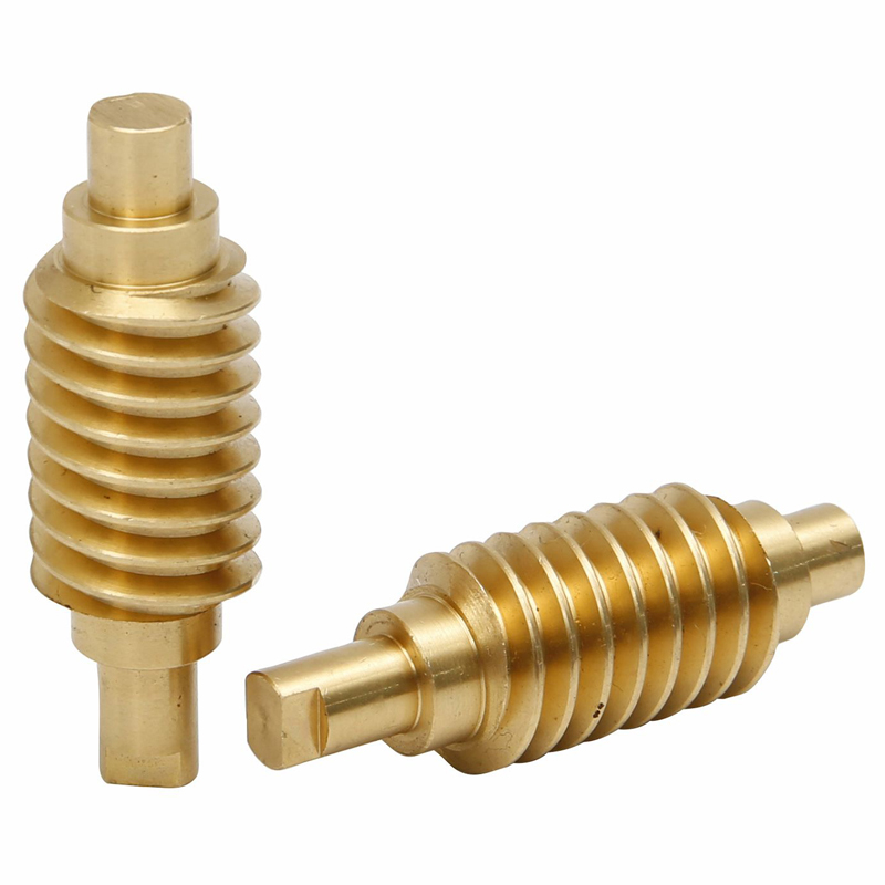
Custom CNC Machined Brass Worm Shaft with Helical Teeth and Stepped Shaft Ends
Description
Product Overview
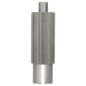
This custom CNC machined brass worm shaft is a precision transmission component featuring a continuous helical tooth profile, stepped shaft ends, and an integrated cylindrical shaft structure. It is designed for compact mechanical transmission systems where controlled rotational motion, reliable torque transfer, and smooth engagement with a mating worm wheel are required.
Unlike a conventional threaded shaft, a worm shaft uses a helical tooth form specifically designed for power transmission. The central worm section works with a compatible worm wheel to transmit rotational motion while providing a substantial speed-reduction capability within a compact mechanism.
The stepped shaft ends provide defined locating and mounting surfaces for bearings, bushings, couplings, or other drive components. One end can also be machined with a flat or other torque-transfer feature according to the customer’s drawing.
Manufactured as a custom CNC turning part, this type of worm shaft can be produced to customer-specified dimensions, tooth geometry, shaft diameters, surface finish, and tolerance requirements.
CNC Machining Specifications
| Parameter | Specification |
|---|---|
| Product Type | Custom Worm Shaft |
| Primary Process | CNC Turning / CNC Machining |
| Functional Category | Gear & Power Transmission Parts |
| Material | Brass; other copper alloys available |
| Worm Profile | Helical tooth / worm profile according to drawing |
| Shaft Structure | Stepped shaft with integrated worm section |
| Drive Feature | Flat, slot, keyway, or custom end feature |
| Dimensional Tolerance | Typically ±0.01 mm; ±0.005 mm achievable on selected features |
| Shaft Diameter Tolerance | According to drawing and functional requirements |
| Tooth / Lead Accuracy | Controlled according to worm geometry and application requirements |
| Surface Finish | CNC machined finish; polishing or additional finishing available |
| Heat Treatment | Available when specified by material and application |
| Inspection | Dimensional inspection and drawing-based quality inspection |
| Production Volume | Prototype, small batch, and production quantities |
| Drawing Formats | 2D drawings, 3D CAD models, STEP, IGES, etc. |
| Customization | Dimensions, worm profile, shaft ends, grooves, flats, and other features |
Note: Actual tolerances depend on the part geometry, material, worm profile, shaft diameter, required inspection method, and drawing requirements. Tight tolerances such as ±0.005 mm should be specified for individual critical features rather than treated as a blanket tolerance for the entire worm shaft.
Why This Worm Shaft Design Matters
The main feature of this component is the combination of a helical worm section and precision-machined stepped shaft ends in one integrated part.
The central helical section provides the working tooth geometry for engagement with a mating worm wheel. The stepped shaft sections establish the rotational axis and provide locating surfaces for supporting components.
This integrated design can reduce the number of separate components in a compact transmission assembly while maintaining a controlled relationship between the worm profile and shaft axis.
For custom CNC machining, the relationship between the worm section, shaft diameters, shoulders, and end features is particularly important because dimensional errors can accumulate across these functional surfaces.
Material Analysis – Brass
Brass is a suitable material for many small and medium-duty worm shafts where machinability, dimensional stability, corrosion resistance, and good surface characteristics are important.
Common brass grades for CNC machining may include C3604, C36000, H59, and H62, depending on the customer’s required mechanical properties and applicable standards.
Advantages of Brass for CNC Worm Shafts
Excellent machinability
Free-cutting brass grades can be efficiently machined by CNC turning, making them suitable for complex profiles containing multiple diameters, shoulders, grooves, and end features.
Good dimensional stability
Brass can maintain consistent dimensions during machining, which is important for shaft journals and locating surfaces.
Good sliding characteristics
Copper alloys can provide useful friction and wear characteristics in selected low-speed or moderate-load mechanical applications.
Corrosion resistance
Brass generally provides better corrosion resistance than ordinary carbon steel in many environments, making it useful for components exposed to normal industrial or indoor conditions.
Good surface appearance
CNC-machined brass can achieve a clean metallic finish and can also be polished or otherwise surface-finished according to the application.
Material Selection
For a production worm shaft, the exact brass grade should be selected according to:
- Required strength and hardness
- Worm/worm-wheel material combination
- Operating speed
- Load and torque
- Lubrication conditions
- Wear requirements
- Machining requirements
For higher-load worm transmission systems, steel or other engineered materials may be more appropriate. Material selection should therefore be based on the actual transmission design rather than appearance alone.
CNC Machining Tolerance Capability
Precision is particularly important for a worm shaft because several features work together as one transmission system.
Critical dimensions may include:
- Worm shaft outside diameter
- Bearing journal diameter
- Shoulder dimensions
- Shaft concentricity
- Axial positioning
- Worm lead
- Tooth geometry
- Tooth depth
- End-face location
- Keyway or drive-flat dimensions
For suitable geometries, XINQIDA can manufacture selected CNC-machined features to approximately ±0.005 mm, while general dimensions may use wider tolerances according to the engineering drawing.
For worm shafts, however, dimensional tolerance alone does not define transmission accuracy. Worm lead, tooth profile, concentricity, runout, and the relationship between the worm section and bearing journals can be equally important.
This is why a production drawing should identify the truly functional features instead of applying an unnecessarily tight tolerance to every dimension.
Manufacturing Challenges of a CNC Worm Shaft
1. Maintaining the Worm Profile
The helical tooth profile is the most important functional feature of the component.
The machining method must be selected according to the required worm geometry, lead, accuracy, production quantity, and equipment capability. Depending on the design, the worm profile may require specialized CNC thread-cutting, milling, hobbing, or other gear-machining processes.
2. Controlling Concentricity
The worm section and shaft journals must maintain a controlled relationship around the same rotational axis.
Excessive runout or eccentricity can affect:
- Worm-wheel engagement
- Noise
- Vibration
- Contact pattern
- Wear
- Transmission efficiency
Therefore, the machining process should establish appropriate datums and inspection references.
3. Managing Multiple Shaft Diameters
The stepped shaft design typically contains several functional diameters and shoulders.
Each diameter may have a different purpose, such as:
- Bearing support
- Component positioning
- Axial locating
- Coupling connection
- Torque transmission
These features must be machined consistently to ensure proper assembly.
4. Preventing Burrs on Helical Teeth
The intersection between the worm tooth profile and machined shaft surfaces can create small burrs.
Poor deburring can affect:
- Assembly
- Tooth engagement
- Surface quality
- Part cleanliness
Controlled deburring and inspection are therefore important after machining.
5. Balancing Accuracy and Production Cost
Not every feature requires ultra-tight tolerance.
Applying ±0.005 mm to every dimension can significantly increase machining time, inspection requirements, and production cost without improving the actual performance of the transmission.
A better approach is to identify the functional dimensions and assign tighter tolerances only where they affect:
Fit + alignment + rotation + transmission performance.
Applications
Custom worm shafts can be used in a variety of compact mechanical transmission and motion-control systems.
Micro Gearboxes
Brass worm shafts can be used in selected compact gearboxes where low-to-moderate torque transmission and compact packaging are required.
Industrial Automation
They can be integrated into small actuators, positioning mechanisms, indexing systems, and other automated equipment.
Electric Actuators
Worm transmission mechanisms are commonly used where controlled movement and compact mechanical reduction are required.
Smart Home Devices
Potential applications include compact mechanisms used in:
- Motorized blinds
- Electric curtain systems
- Smart locking mechanisms
- Small lifting mechanisms
Instrumentation
Small precision transmission components can be used in instruments and electromechanical mechanisms where controlled rotational movement is required.
Automotive Auxiliary Mechanisms
Depending on the material, load, durability, and qualification requirements, worm transmission components can be used in selected auxiliary adjustment or actuation mechanisms.
Custom Worm Shaft Manufacturing
XINQIDA manufactures custom CNC machined transmission components according to customer drawings, CAD models, samples, and application requirements.
For a custom worm shaft, the most useful information for manufacturing evaluation includes:
- Overall shaft dimensions
- Worm outside diameter
- Worm lead and tooth geometry
- Number of starts
- Shaft journal diameters
- Bearing fit requirements
- End-drive configuration
- Material grade
- Surface finish
- Critical tolerances
- Required quantity
For complex worm profiles, a 2D engineering drawing together with a 3D CAD model is preferred because the 3D model helps define the overall geometry while the drawing establishes the functional dimensions and tolerances.
Quality Inspection
Each custom worm shaft can be inspected according to the customer’s drawing and quality requirements.
Typical inspection items include:
- Overall dimensions
- Shaft diameters
- Shoulder locations
- Concentricity
- Runout
- End-face dimensions
- Worm outside diameter
- Tooth/profile dimensions
- Lead-related requirements
- Surface finish
- Burrs and visual defects
For higher-precision transmission components, inspection requirements should be agreed before production so that the appropriate measuring equipment and acceptance criteria can be defined.
Frequently Asked Questions
What is a worm shaft?
A worm shaft is a rotating transmission component with a helical worm profile. It normally works with a worm wheel to transmit rotational motion and achieve significant speed reduction in a compact mechanism.
Is a worm shaft the same as a threaded shaft?
No. Although both have a helical profile, a conventional threaded shaft is generally designed to engage with a nut for fastening or linear motion. A worm shaft is designed as a power-transmission component and works with a compatible worm wheel.
Can you CNC machine brass worm shafts?
Yes. Brass is highly machinable and is suitable for CNC turning and other precision machining processes. The appropriate brass grade should be selected according to the required strength, wear resistance, operating conditions, and transmission design.
What brass grades can be used for CNC worm shafts?
Depending on the application and drawing requirements, possible grades include C3604, C36000, H59, and H62. The final material should be specified according to the applicable material standard and customer requirements.
What tolerance can you achieve on a worm shaft?
For suitable CNC-machined features, tolerances around ±0.005 mm can be achievable. However, the actual capability depends on feature size, geometry, material, machining process, and inspection requirements. Worm lead, profile, concentricity, and runout may be more important than general dimensional tolerance for transmission performance.
Can you manufacture worm shafts from customer drawings?
Yes. Custom worm shafts can be manufactured from 2D engineering drawings, 3D CAD files, or approved samples. The drawing should specify the worm geometry, material, critical dimensions, tolerances, and surface requirements.
What is the difference between a worm shaft and a lead screw?
A worm shaft is primarily designed to transmit rotational power through engagement with a worm wheel. A lead screw is normally designed to convert rotational motion into controlled linear movement through a mating nut. Their helical geometries may look similar, but their tooth profiles and functional requirements are different.
Can you manufacture small-batch worm shafts?
Yes. Custom CNC machining can support prototype, low-volume, and production quantities. The manufacturing process can be selected according to the required accuracy, worm geometry, quantity, and production cost.
Request a Custom Worm Shaft Quote
If you need a custom CNC machined brass worm shaft, send us your 2D drawing or 3D CAD model.
Our engineering team can review:
- Material selection
- Worm profile
- Critical tolerances
- Shaft and bearing fits
- Machining feasibility
- Inspection requirements
- Production quantity
Get a Free DFM Review & Quote for Your Custom Worm Shaft.


Reviews
There are no reviews yet.