
In modern precision manufacturing, CNC (Computer Numerical Control) machining—including milling, turning, and drilling—has become a core production method thanks to its high accuracy and efficiency. However, CNC machining is not a universal solution. Beyond the commonly known issue of curved holes, several geometric features and structural designs fall into CNC machining “no-go zones.”
If these features are forced into a design, they may lead to machining failure, scrapped parts, increased production costs, and delayed delivery schedules. This article highlights several commonly overlooked machining limitations and provides practical alternative solutions to help designers and manufacturers avoid costly mistakes.
Table of Contents
Toggle1. Key “No-Go Zone” Features in CNC Machining
1. Curved Holes: A Classic CNC Limitation
CNC machining relies on linear movement along the X, Y, and Z axes or rotational motion within a single plane. Cutting tools move in straight paths or simple arcs, which means they cannot follow complex spatial trajectories.
As a result, holes that bend through multiple planes—such as 90-degree L-shaped holes or curved channels along surfaces—cannot be machined using standard CNC methods. Attempting to machine such features may result in tool collisions, damaged workpieces, or holes that deviate significantly from the design.
2. Deep and Narrow Blind Holes: The Hidden Risk
Deep narrow blind holes have clear process limitations in CNC machining. In most cases, when the depth-to-diameter ratio exceeds 10:1, the feature becomes difficult and risky to machine.
There are two main challenges:
Tool deflection and vibration: Long, slender cutting tools may bend or vibrate, causing tapered holes, dimensional errors, or even tool breakage.
Chip evacuation problems: Chips accumulate inside deep holes, scratching the surface, clogging the tool, and generating excessive heat that can damage the workpiece.
These features frequently appear in hydraulic valve blocks, molds, and cooling channels, making them a common CNC machining challenge.
3. Ultra-Small Features: Beyond Tooling Limits
When a design includes features smaller than the minimum available cutting tool diameter, CNC machining becomes impossible.
Examples include:
Micro holes with diameters around 0.1 mm
Slots narrower than 0.08 mm
Micro recesses only 0.05 mm deep
Standard CNC tools typically have minimum diameters around 0.2 mm, and smaller tools lack the rigidity needed to withstand cutting forces, making breakage highly likely. Such ultra-small features are common in precision sensors and micro medical devices, placing them outside the practical range of conventional CNC machining.
4. Undercuts and Enclosed Internal Cavities: Machining Dead Zones
Undercuts refer to recessed features that interfere with the tool’s movement direction, such as:
Circular grooves on external surfaces
Reverse protrusions on the inner walls of holes
Fully enclosed internal cavities present an even greater challenge, as there is no entry path for cutting tools.
Since CNC tools must approach the machining area from outside the part, these structures create machining dead zones that standard tools cannot reach. These features are commonly found in snap-fit components, molds, and complex internal fixtures.
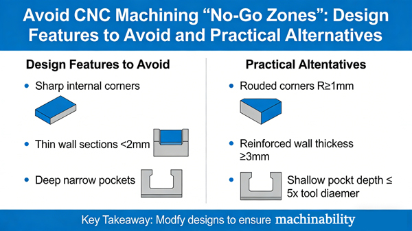
5. Extremely Thin Walls: Deformation Risks
Thin-wall structures with thicknesses below 0.5 mm or ribs narrower than 0.3 mm are considered high-risk features for CNC machining.
During cutting:
Machining forces can cause elastic or plastic deformation
Internal stresses may lead to warping or distortion after machining
Thin walls are also vulnerable to damage during clamping
These issues frequently arise in lightweight components, consumer electronics housings, and precision instruments.
2. Alternative Manufacturing Solutions for These Features
When these design features cannot be avoided, alternative manufacturing technologies can help achieve the required geometry while maintaining precision and production efficiency.
| Challenging Feature | Alternative Process | Advantages | Typical Applications |
|---|---|---|---|
| Curved holes | Electrical Discharge Machining (EDM) | No physical contact between tool and workpiece; electrodes can be shaped to match complex paths; accuracy up to ±0.005 mm | Aerospace components, medical implants, mold manufacturing |
| Deep narrow blind holes | Deep hole drilling with high-pressure chip evacuation | Specialized drills and cooling systems allow depth-to-diameter ratios up to 30:1 with smooth surfaces | Hydraulic valve blocks, engine cooling and oil channels |
| Ultra-small features | Laser micromachining or electron beam machining | Beam diameter as small as 0.001 mm; no physical tool contact; suitable for micron-scale features | Micro sensors, medical device components |
| Undercuts / enclosed cavities | EDM sinker machining + split-component design | Custom electrodes allow machining of undercuts; enclosed cavities can be produced through segmented parts and post-assembly | Mold cavities, automotive tooling, precision fixtures |
| Extremely thin walls | 3D printing (additive manufacturing) + secondary CNC finishing | Additive manufacturing forms thin structures without cutting forces; CNC finishing ensures final dimensional accuracy | UAV housings, electronic frames, precision equipment |
3. Design Principles to Avoid CNC Machining Limitations
To prevent manufacturing issues from the start, designers should integrate Design for Manufacturability (DFM) principles during product development.
1. Design with CNC Capabilities in Mind
Avoid curved, enclosed, or extremely small features whenever possible. Instead, favor straightforward geometries, open structures, and standard dimensions.
For example:
Replace curved channels with multiple intersecting straight holes
Convert undercuts into open slots or accessible grooves
2. Collaborate with Manufacturing Engineers Early
Engage CNC machining specialists during the early design stage to understand machine capabilities, tooling limits, and process parameters.
Early communication helps confirm:
Maximum feasible depth-to-diameter ratios
Minimum tool sizes
Material-specific machining limitations
This approach prevents costly redesigns later in the production cycle.
3. Combine Manufacturing Technologies
For complex components, consider hybrid manufacturing strategies.
For instance:
Use CNC machining for the main structure
Apply EDM or additive manufacturing for difficult features
This combination balances manufacturing efficiency, cost, and feasibility.
Conclusion
While CNC machining is a powerful manufacturing technology, it has clear technical limits. In addition to curved holes, features such as deep narrow blind holes, ultra-small structures, undercuts, and extremely thin walls are common design pitfalls.
By identifying these machining limitations early, selecting suitable alternatives such as EDM, laser micromachining, or additive manufacturing, and following design-for-manufacturability principles, engineers can significantly reduce production risks, lower costs, and shorten lead times.
Ultimately, successful precision manufacturing depends on balancing innovative design with realistic manufacturing capabilities—ensuring that every concept can be efficiently transformed into a high-quality, manufacturable part.
