
In CNC machining, many designers are surprised to find that actual machining costs far exceed their initial estimates. In most cases, the root cause lies in improper fillet (R-corner) design.
Small fillets are often rejected during manufacturability reviews, while sharp internal corners significantly increase machining steps—both quietly driving costs upward.
Based on real-world machining practice, this article breaks down the manufacturing logic behind fillet design and summarizes three proven design rules for CNC-friendly R corners, along with two cost-effective alternatives for unavoidable sharp corners. Applying these principles early in the design stage can greatly reduce machining complexity and overall production cost.
Table of Contents
ToggleWhy Fillets Are Inevitable in CNC Machining
To design fillets correctly, it’s essential to understand why R corners exist in CNC machining.
A CNC end mill is fundamentally a rotating cylindrical tool with cutting edges. Due to its geometry, any internal corner machined with an end mill will naturally form a radius equal to the tool radius. This internal fillet is an inherent characteristic of CNC milling, not a limitation that can be eliminated through conventional processes.
As a result, the size of the fillet directly influences tool selection, machining strategy, cycle time, and cost.
How Poor Fillet Design Drives Up Machining Costs
Unreasonable fillet design is one of the most common causes of rising CNC machining costs:
Overly small fillets require smaller-diameter tools, which remove material more slowly, have lower rigidity, and are more prone to vibration or breakage—leading to longer machining times and higher costs.
Sharp internal corners cannot be produced using standard milling tools. Achieving them usually requires additional EDM (Electrical Discharge Machining) operations, which significantly increase both lead time and price.
For this reason, avoiding sharp internal corners and using appropriately sized fillets is one of the most effective ways to reduce CNC machining costs.
The core design principle is straightforward:
The larger and more consistent the fillet radius, the better.
Three Golden Rules for CNC Fillet Design
The following three best practices are widely accepted in CNC manufacturing and can help minimize machining difficulty and cost.
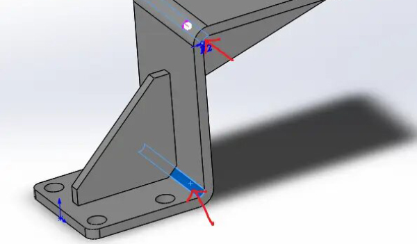
1. Fillet Radius ≥ One-Third of the Slot Depth (Bigger Is Better)
For internal corners, the fillet radius should be at least one-third of the slot depth. Larger radii allow the use of larger-diameter tools, which improves rigidity and machining efficiency.
For example, for a slot with a depth of 12 mm, an ideal fillet radius would be 4 mm or larger. This enables the use of an 8 mm or larger end mill, resulting in faster cutting speeds and better surface quality.
2. Fillet Radius Should Be Larger Than the Tool Radius
When the fillet radius is equal to or smaller than the tool radius, the cutter enters a full-width engagement at the corner. This causes a sudden increase in cutting load, leading to tool chatter, poor surface finish, dimensional inaccuracies, and reduced tool life.
A better approach is to design the fillet radius slightly larger than the tool radius.
For instance, when using a 10 mm diameter end mill (5 mm radius), the internal fillet should be designed as R6 or larger. This allows for smoother load transitions, improved chip evacuation, and more stable cutting conditions.
3. Standardize Non-Critical Fillet Sizes
For non-functional or non-critical internal corners, it is strongly recommended to standardize the fillet radius across the entire part, such as using R3 or R5 consistently.
This enables most machining operations to be completed with a single tool, reducing tool changes, setup time, and programming complexity—ultimately improving efficiency and lowering manufacturing cost.
Two Low-Cost Alternatives to Sharp Internal Corners
In some applications, sharp or square internal corners are functionally necessary for assembly or mating requirements. Forcing conventional machining methods in these cases often leads to excessive costs. Instead, the following alternatives are commonly used:
1. Add Relief Grooves or Corner Clearance Slots
At locations requiring sharp corner mating, a small relief groove or clearance slot can be added to provide tool clearance and avoid interference.
Compared with EDM corner clearing, this approach is significantly more cost-effective and is often the preferred solution when sharp corners are required for functional rather than aesthetic reasons.
2. Clearly Specify EDM Requirements on Technical Drawings
If sharp internal corners are absolutely critical and must be produced using EDM, this requirement should be clearly specified on the 2D drawing with explicit process notes.
Clear instructions help avoid repeated quotation clarifications, reduce miscommunication, and prevent rework or process deviations—saving both time and cost during production.
Cost Control Starts at the Design Stage
CNC machining cost control does not begin on the shop floor—it starts at the design stage.
As one of the most fundamental yet impactful design details in CNC machining, fillet radius selection directly affects machining methods, efficiency, and cost. By following the principles of larger and standardized fillets, and by adopting low-cost alternatives when sharp corners are unavoidable, designers can achieve optimal manufacturability without compromising functional requirements.
These production-proven design practices are widely used in mechanical and industrial design to control machining cost from the source.
